Use smart instrumentation to prevent dangerous, costly spills at your processing plant
In the process industries, safety is the linchpin for reliability, productivity, and profitability—whether during construction, commissioning, daily operation, or any other phase of a facility’s lifecycle. Without the necessary precautions in place, companies cannot sustain other objectives with any sort of consistency, a truth that has led to the establishment of safety standards.
One of these standards mandates every plant storing chemicals or other hazardous process media in tanks must develop and maintain an effective spill prevention, control, and countermeasure plan. Such preparation is imperative to protect the facility, the environment, and plant personnel.
Spills are typically the result of tank overfill or process leaks, and these are conditions that can be prevented or detected early but often are not discovered until sizable damage ensues. This article discusses standards and practices aiming to mitigate these sorts of events, along with the benefits of smart instrumentation in supporting these efforts.
Random versus systemic failure
Most failures that cause industrial incidents, including spills, are not random but instead are systemic. A 2003 study by the United Kingdom Health Safety and Environmental Committee found 65% of all plant failures were caused by systemic issues such as mistakes in specification, design and implementation, or installation and commissioning (see Figure 1).
Random failures are caused by hardware issues, such as electronic components that degrade over time. While the risk of random failure cannot be entirely eliminated, it can be managed through regular proof testing to detect and address potential issues early.
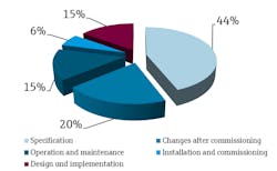
By contrast, systemic failures are linked to deficiencies in system design or maintenance planning. They are almost completely avoidable through careful engineering, and standards like IEC 61508 and 61511 provide guidelines for reducing these failures in a variety of applications, including tank filling.
SIS development standards
The American Petroleum Institute (API) 2350 standard provides generic minimum requirements for preventing tank overfills, which can be fulfilled by implementing a safety instrumented system (SIS) in accordance with the IEC 61508 and 61511 standards.
IEC 61508 describes methods for developing and applying safety systems across a broad range of industries, addressing application safety integrity level (SIL) and other requirements. Instrumentation manufacturers can receive SIL certification for their devices through compliant design processes, and using certified instrumentation lowers the risk of systemic errors throughout service life for end users.
IEC 61511 requires an SIS to adhere to a safety requirements specification (SRS) in order to ensure that it performs its function reliably. An SRS is a document that describes all aspects of the safety system, including architecture, commissioning, and maintenance requirements. By carefully executing a well-planned SRS, errors and oversights are less likely in deployment.
Upholding these standards requires regular proof testing of safety devices, which in tank filling applications include level switches, signal horns, and beacons. Every element of a SIS must be independent from the basic process control and related systems to maintain its integrity. To reduce the risk of improper configuration, many applications use a pre-engineered SIS with built-in, systemwide proof testing functionality, saving time and money during commissioning and operation.
Level switches
In overfill prevention systems, relying solely on primary continuous level technology is a potential risk, due to dependance on a single point of failure. However, this concern can be addressed by including an appropriate point level device in a dedicated SIS to supplement overfill detection. In addition to a high-level switch located at the maximum fill point for normal operation, mounting a high-high level switch above this point is typically best practice to generate an alert when it is triggered (see Figure 2).
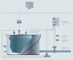
Retention dikes surrounding tanks also can completely contain some spillage to help minimize impact in the event of an overfill or leak. Equipping these dikes with level switches provides an additional layer of information for detecting spills. To distinguish between process and other fluids, such as rainwater, distinct types of level switches can be used in conjunction. For example, a conductivity switch will detect rainwater but not hydrocarbon fluids, while a vibronic “tuning fork” switch will detect both. By installing both switch types in a retention dike, operators can monitor for the presence and type of fluid.
Advantages of smart instrumentation
Regular testing of SIS level switches is critical because several years can pass between operational activation. Under API 2350, it is not permitted to intentionally elevate tank fluid to an unsafe level, so most facilities remove these switches for testing. However, switch removal interrupts both operations and personnel availability, and manual removal, testing, and reinstallation of safety devices can result in errors or instrumentation damage.
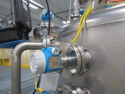
Addressing these and other issues, modern smart level switches support automated, in-situ testing, thus minimizing manual intervention and the risk of systemic failure (see Figure 3). When in-situ testing is not possible, guided proof tests built into smart instruments can reduce the potential for error by providing step-by-step instructions and comprehensive verification reports. And upon instrument replacement, smart tools can confirm a configuration match between the old and new devices. Once configuration is complete, device settings can be locked to prevent unauthorized changes, and reports can be generated to verify standards compliance.
In addition to automated verification, these instruments continuously monitor and transmit diagnostic information, which can be incorporated into notification systems to alert operators of developing issues. Because sensors often begin deteriorating prior to failure, automated diagnostics provide the foundation for predictive maintenance, allowing staff to focus efforts where most needed to maintain uptime.
In one application, a chemical manufacturer sought to proof test their SISs more frequently to reduce the risk of spills. The application included four interconnected tanks of thionyl chloride, which is acutely toxic. Previously, conventional proof testing of the level switches in these tanks occurred yearly, and it was an arduous task because instrument removal was required. This procedure mandated entirely emptying and cleaning the tanks, and technicians needed to wear full body protection when removing and subsequently reinstalling the instruments. The inherent risks included significant downtime, instrumentation installation errors, and human safety concerns.
To increase SIS functional confidence while minimizing maintenance efforts and downtime, the plant replaced its conventional sensors with smart vibronic “tuning fork” level switches, ensuring reliable point level detection as part of a SIL3 safety loop. Each of the four tanks is equipped with its own switch, providing homogenous redundancy and minimizing the likelihood of system failure, even if an individual switch fails. And because the chosen switch model was developed in accordance with IEC 61508 requirements for SIL3 functional safety, the facility did not need to perform additional risk reduction analysis after installation.
Each year, or more frequently, technicians initiate an automated, in-situ proof test for each switch without any process interruptions, and complete removal and full testing is now required just every three years. Between scheduled proof tests, the switch self-monitors and provides warning of any unusual changes in vibration frequency, which signifies a problem.
Careful design leads to safe implementation
Preventing tank overfills begins with informed hardware specification and system design, and it culminates with the implementation of safety systems with the right level instrumentation and reliable verification procedures.
Selecting certified smart instrumentation provides many safety and efficiency advantages, including ongoing diagnostic monitoring, commissioning wizards, automated verification, onboard reporting, and long intervals between comprehensive proof tests. Collectively, these capabilities increase facility uptime, reduce the risk of systemic error associated with instrument removal and reinstallation, and empower migration from reactive manual maintenance to focused predictive maintenance programs.
1 United Kingdom Health and Safety Executive. Out of control: Why control systems go wrong and how to prevent failure, 2003.
About the Author
Keith Riley
Endress+Hauser
Keith Riley is the National Product Manager for Level and Pressure at Endress+Hauser. He has been with the company since April 2008. Prior to this, he was a Product Manager and Regional Sales Manager with L.J. Star Incorporated, as well as a Product Manager for Penberthy (Tyco Valves). Overall, he has over 20 years of sales, marketing, and instrumentation experience in the process industries.
Kris Worfe
Kris Worfe is the Chemical Industry Manager at Endress+Hauser USA. He has national responsibilities for the strategic direction of the chemical business, including product portfolio management, technical and application support, and marketing and business development for the chemical industry. He has a BBA from Texas A&M University. Based out of Houston, TX, Kris has over 22 years of process automation experience.