How to improve your troubleshooting process for rotating equipment
In a large complex with thousands of pieces of rotating equipment, the goal of predictive maintenance (PdM) work is to distinguish any bad actors from those that are not. Once an abnormal state is identified, concerns include: Is the asset crying wolf? How long it can last in operation? What action ought to be taken? Which mechanical component needs to be replaced?
All involved in this work expect to diligently search for latent defects and investigate their source in order to justify a necessary and efficient shutdown. Therefore, “no news is good news” is always a motto before blowing the first whistle, and of course blowing it at the right time.
Vibration analysis is a well-recognized and useful reliability tool for application on rotating equipment. It is not only effective but also un-intrusive, as machine health information can be acquired without interrupting production. Vibration is a phenomenon that only occurs when the asset is running but is also a fugitive phenomenon. It disappears immediately after asset shutdown, and taking vibration readings on idle equipment is meaningless.
With vibration analysis, the machine speaks for itself by expressing a visible trend relative change; however, what is physically happening inside the asset is not self-explained. Although vibration data never lies, the analyst must determine the meaning of the data. For example, unique Operation Deflection Shape (ODS) has amplified vibration response under specific loading but without a defect. Therefore, the first goal of the analyst would be to distinguish mechanical deterioration from process change, and the second goal would be to determine the nature of the defect.
Many defects, from A to Z, can be on list. Bearing failure with its scary and complicated outward is one of them and not un-usual, signal processing to extract buried failure mechanism information under noise floor to point out the damaged nuances (inner race, outer race, rolling elements and cage) was well developed.1 Accurate severity evaluation for each failure stage from initial until the last minute is possible if enough data is available.2
1x RPM: The footprint of unbalance
The expression “1x” means vibration at the same frequency as the running speed of the machine. Unique vibration fingerprints like blades pass, gear mesh, electrical rotor bar passing, etc., are all derived from the 1x RPM, which is the basic vibration metric.
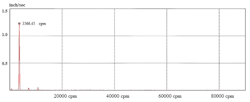
The dynamic behavior of unbalance is well studied, and unbalance with single peak at 1x rotating speed in Fast Fourier Transformation (FFT) spectrum is illustrated in Figure 1. Do not take its simplicity for granted. Troubleshooting on a single peak is not as easy as what a first impression might suggest. Defects such as soft foot, misalignment, resonance, and looseness to bent shaft all might have the same brief spectrum appearance: a single peak at 1x RPM.
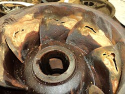
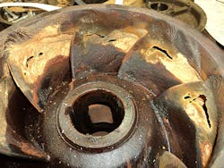
Even if unbalance is isolated from all the other defects and confirmed to be the only defect, unbalance still can be induced by a long list of fault modes, like corrosion/erosion (Figure 2), un-even porosity flaws during manufacturing, process material build-up, oversize key, and un-symmetrical electrical winding coils. Sometimes, the root cause is impressive; for example, vibration during startup can be amazing after the motor was idle for months, because a big wasp nest is built on the motor cooling fan.
The following are rules of thumb to narrow down unbalance to be the root cause of failure on a given asset:
- Its FFT spectrum (Figure 1) has a peak only at 1x rotating speed.
- Its associated waveform (Figure 3) is periodic sinusoid fluctuation at 1x rotating speed.
- Amplitude at 1x rotating speed is about the same dynamic range along different directions.
- Phase shift at 1x rotating speed is at same pace with sensor physical orientation alteration (for example, if you move sensor on a pedestal from the 12:00 to 3:00 position, the phase shift should change 90 degrees; a change from 12:00 to 6:00 position should change the phase shift by180 degrees)
Occasionally, vibration might be amplified if 1x rotating speed is close to a natural frequency at a specific location, which excites resonance and violates the above rules of thumb. For example, amplitude along horizontal is three times higher than vertical; phase shift is 0° (or 180°) instead of 90°, as described. Other than resonance, misalignment, weak foundation, soft foot, and looseness have influence as well, since all are originated from the same source, the 1x rotating speed and overlapped at the same frequency line. Add up is applied if the defect is in phase (0°) with unbalance, or cancel each other if the defect is out of phase (180°) with unbalance, or between.
Under such circumstances, it is hard to conclude that unbalance is the root cause. The condition is also tough to correct, since how much trial weight is required and where to attach it can never be accurate. Therefore, it is critical to eliminate all other possibilities (i.e., fix apparent defects like soft foot, excessive bearing looseness, cracked foundation, etc.) before declaring unbalance to be the only troublemaker.
An appendix behind Diagnostic Chart
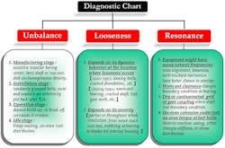
Even if every rule of thumb is satisfied, and unbalance is confirmed to be the bad actor and turned over to the millwright, what that person gets is just a vague direction: yes, unbalance must be and is the sole root cause, but where does it come from and in what format? A Diagnostic Chart is the primary fishbone; however, its extended branches can be endless. That is the purpose for discussion, to add an appendix to the diagnostic chart for rotating equipment.
The Diagnostic Chart presented in Figure 4 is only used as a reminder for veterans or as a practical training tool for novices. Other defects can be added by analysts based on their unique experience to make the chart more thorough. (Note: For the sake of readability, Figure 4 only showcases unbalance, looseness, and resonance; other major defect categories like bearing and misalignment are not highlighted).
Precise balancing (the last but not the least appendix)
Once unbalance is corrected and the trend comes down, does it mean the job is over? Not necessarily. If the only goal is to minimize vibration caused by unbalance and recover production as soon as possible, the simple answer is yes. However, this approach only provides a temporary break on bearing and its imminent support structure, not the rotor itself, resulting in a sensible but superficial balancing.
Balancing is a procedure to improve the mass distribution to reduce the centrifugal force while a rotor is rotating. In the meantime, even unbalance is diagnosed to be the only bad actor, however, on a multiple stages train, where the original unbalance is still unknown and each component can make its own contribution; fortunately, their lump sum can be combined into a single virtual vector & put a weight to create a 180° opposed force for a disk (like impeller) or opposed forces in pair and their associated reverse moment, if the part (like spool coupling) is slender along the shaft axial direction.
As a temporary antidote, field balancing, can reduce high vibration appreciable by human, however, the internal stress does not,3, 4, 5 which is a silent killer. Take an 1800 RPM rotor for example; with any existing fatigue stress, it repeats more than 946 million cycles a year, for 24/7 operation. Figure 5 is a shaft broken by rotational bending fatigue failure mode, which slowly develops from origin (left upper corner) at early stage before sudden failure at Instantaneous Zone (right lower corner) without warning. That is why each component on a multiple stages train (impeller, gear, coupling, pulley, shaft, etc.) needs individual balancing first and a final trim after having been assembled together to eradicate the side effect, which is stress fatigue or stress when it is rotating. Precise balancing is the only way to remediate this defect, and can be done during manufacturing or major turnaround. There is no short cut.
References
1. Description of PeakVue and illustration of its wide array of applications in fault detection and problem severity assessment, presented at Emerson Process Management Reliability Conference, 2001, Oct/22-25, by James C. Robinson, CSI, an Emerson Electric Company and James E. Berry, P.E., Technical Associates of Charlotte, P.C.
2. Alarm management of permanent vibration monitoring on a slow speed gearbox, presented at 2014/July, Uptime Conference, by Han-Chian Gee (related link: https://reliabilityweb.com/articles/entry/alarm_management_of_permanent_vibration_monitoring_on_a_slow_speed_gea)
3. Formulas for stress and Strain (Raymond J. Roark and Warren C. Young)
4. Rotor balancing for bearing reliability, 2001/June, Plant Services, by Han-Chian Gee (related link: https://www.plantservices.com/equipment/industrial-motors/article/11332745/rotor-balancing-for-bearing-reliability
5. Fundamentals of Balancing, Third Edition, April 1990, published by Schenck Trebel
About the Author
Han-Chian Gee
Han-Chian Gee is a chief maintenance engineer for Formosa Plastics Corp, Point Comfort, TX, one of the top PVC suppliers in the world. He has more than 30 years of experience on rotor dynamics and other related reliability practices and technologies. He is an ISO 18436-2 Category III certified analyst and a registered PE in the state of Texas. He previously worked at Aerospace Industrial Development Corporation (AIDC), Taiwan, on the fuselage, on a composite (graphite) design for speed brake, on a honeycomb horizontal stabilizer, and on the rudder for AT-3 jet trainer & Indigenous Defense Fighter (IDF). He can be reached at: [email protected]
