Part 1 of this two-part article appeared in the October 2006 issue. It discussed different way to quantify compressor efficiency and operation schemes that can lead to energy savings. View Part 1.
Much of the VSD compressor’s popularity is a result of marketing spin. Often, free audits exaggerate paybacks by including savings the end user can achieve without purchasing a VSD compressor. The marketers also fail to provide the necessary engineering details required to maximize the purported benefits. It’s time to eliminate the spin and point out both the limitations and engineering required if you are to derive the benefits of a VSD compressor.
Power factor
The spinners claim there are no penalties for spikes or low power factor. In the limited context of the compressor, this statement is true and refers to the fact that the VFD provides a soft start similar to a Wye-Delta or electronic starter and that the power factor of a motor on a VSD compressor is close to unity over the complete speed range. A unity power factor is a benefit and it can reduce energy costs if the VSD motor constitutes a significant portion of the plant’s motor load. On the other hand, if the local utility doesn’t have a power factor penalty or the VSD compressor constitutes only an insignificant portion of the motor load, then a unity power factor offers little cost benefit.
Free energy analysis
The spinners offer free energy analyses or audits. The old adage, you get what you pay for applies here. Many compressor manufacturers gear these free audits to get their sales personnel into a plant to sell equipment. Free air audits don’t address pressure drop, piping, air quality, risk of an outage or demand-side issues. Nor do they offer any non-equipment solutions.
The whole process is automated so it produces an equipment quote for the sales personnel regardless of expertise or experience in the industry. When clients ask us to review these free audit reports, we generally find that the salesperson has misinterpreted the data, the proposals are incomplete, and plant personnel can achieve the majority of the projected savings without purchasing any compressor.
Turndown
At a 100-psi operating pressure, many lubricated VSD compressors can regulate capacity from 100% down to 15% before they must operate in either start-stop or load-unload mode. Spinner literature suggests that all VSD compressors have the same turndown capability, but the fact is that at 100 psi, some can only regulate output capacity from 100% down to 55%.
In addition, turndown range decreases as discharge pressure increases. For example, at 125 psi, the turndown can be as little as 40%, from 100% capacity to 60% capacity.
Turndown range is important to VSD compressor selection because a smaller turndown decreases the purported savings, increases the size and frequency of pressure swings, and can result in compressors short cycling. Or, it can increase the cost to integrate the VSD compressor into the system properly. In summary, turndown varies significantly among compressor manufacturers, models and pressure settings.
Nameplate horsepower
The actual horsepower size of a VSD compressor can be confusing because spinners often play games with the motor nameplate data. For example, a motor might be a 125-hp unit with a 1.15 service factor or a 100-hp motor with a 1.4 service factor. The motor manufacturer can nameplate the motor either way. This practice has resulted in end users installing undersized electrical circuit breakers. In summary, it’s important to determine the actual power applied at full load at the operating pressure to understand efficiency and installation requirements.
Constant pressure
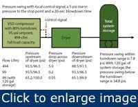
The spinners claim that VSD compressors hold pressure within 1.5 psi. The truth is that VSD compressors are only capable of maintaining the pressure at their discharge within 1.5 psi over their turndown range. You must properly integrate the VSD compressor into your system if you want to prevent larger pressure swings.
{pb}Table 1. Operating a VSD compressor outside of its turndown range can promote large pressure swings.
For example, a VSD compressor requires a signal from a pressure transducer located downstream of the cleanup equipment if it is to prevent changes in pressure drop across the cleanup equipment from increasing system pressure swings. If the control signal is on the compressor, the smallest pressure swing possible is 7.8 psi within the VSD compressor’s turndown range. To reduce the pressure swings, we can either oversize the dryer or just move the control signal to the downstream side of the cleanup equipment, which can reduce the maximum pressure swing, within the compressors’ turndown range, to 3.0 psi.
If you’re operating within the turndown range of the VSD compressor, storage isn’t required, except to ride through sizeable system events. As Table 1 shows, you can’t prevent larger pressure swings from occurring when the VSD compressor operates outside its turndown range or when base-load compressors load and unload.
Storage
Adding sufficient storage minimizes the pressure swings that occur when the VSD compressor operates below minimum turndown or when base-load compressors load and unload. Understanding why pressure swings occur requires an explanation of how VSD compressors operate below minimum speed.
Consider a single compressor system that uses a VSD unit that stops when demand is less than its minimum capacity. As demand decreases, the compressor reduces motor speed to its minimum. If demand continues to fall, the pressure rises to the stop point, which is normally set 5 psi above the target pressure and the VSD compressor shuts down.
Some lubricated VSD compressors blow down the sump when they stop. When the pressure drops to the target pressure, the compressor starts immediately, but the VFD drive needs approximately 10 seconds to ramp up to minimum speed.
If the VSD compressor doesn’t blow down when it stops and pressure drops to the target pressure, a blowdown valve opens and the sump pressure must drop to 55 psi or 60 psi before the VSD compressor starts. The blowdown timer is adjustable so the startup requires between 15 sec and 25 sec. The size of the storage required to minimize the pressure swings is directly proportional to startup time and inversely proportional to turndown.
Compressor manufacturers recommend 1 gal. to 2 gal. of storage per cfm for VSD compressors, but this means there’s a different guideline for each compressor type. To eliminate this problem, use the following rule for all rotary-screw compressor operating modes:
Given a 10-psi differential, storage must equal 5 gal. to 10 gal. per cfm of that portion of the trim compressor’s capacity operating load/unload or start/stop.
Until recently, we’ve always recommended 10 gal. per cfm, but today’s receiver prices require us to consider 5 gal. per cfm, which is the minimum required to prevent short cycling. For example, if the 494 cfm compressor in the table were a load/unload compressor, we’d recommend 2,500 gal. to 5,000 gal. of storage. The reason is that when the compressor unloads, it unloads 100% of its capacity. However, because the compressor is a VSD compressor having an 80% turndown, it only unloads 98 cfm of the compressor’s capacity when it starts and stops, so we would recommend 500 gal. to 1,000 gal. of storage. Note that this guideline doesn’t take into consideration any system events such as the failure of the largest compressor.
In a perfect system having multiple base-load rotary screw compressors operating in load/unload mode and a VSD trim compressor, the VSD unit would never operate below its minimum speed and the capacity of the base-load compressors, which would be less than the turndown capacity of the VSD compressor. This design points out the importance of turndown on VSD compressors.
For example, to prevent the VSD compressor from starting and stopping in a system where, at times, the VSD compressor is the only unit operating, the low load demand must exceed the minimum speed capacity of the VSD compressor. Designing a system in this manner minimizes the storage but increases capital costs because it requires at least one additional base-load compressor. On the other hand, if we use base-load compressors with a capacity larger than the turndown capacity of the VSD compressor, we may short cycle the base-load compressor unless we add additional storage.
For example, assume the base-load compressor capacity is 500 cfm and the capacity and turndown of the VSD compressor are 470 cfm and 80%, respectively. When the base-load compressor unloads, the VSD compressor can supply only 376 cfm (470 cfm * 0.8). This means that demand will exceed the online compressor capacity by 124 cfm. Based on a minimum cycle time of 90 seconds, which most rotary screw compressor manufacturers recommend to prevent short cycling, and a 5-psi differential, we must have minimum system storage of 2,045 gal
(((124 cfm*90 sec/60 sec) / (5 psi * 2)) * 14.7 * 7.48)
We can increase the cycle time to 3 min. by increasing the stop pressure 5 psi to 10 psi above the VSD compressor target setpoint or by doubling the storage.
In summary, you need storage for a VSD compressor in a system having multiple compressors if you want to prevent significant drops in pressure during base-load compressor startup. Also, storage prevents short cycling the base-load compressors, which can occur when their capacity exceeds the turndown capacity of the VSD compressor.
VSD vs. pressure/flow controller
Spin doctors often equate a VSD compressor’s pressure control with a pressure/flow controller with control storage. But, we must point out that a VSD compressor responds to all events using its brute strength horsepower and can’t keep the next compressor from starting. On the other hand, a pressure/flow controller with sufficient control storage responds to events with stored air, which can prevent the startup of the next compressor while maintaining the system pressure within 1% of its setpoint.
Integrating VSD into your system
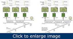
Figure 1. An integrated VSD compressor in a multi-compressor system (courtesy Dean Smith at [email protected]). The left sides represents increasing demand, the right side represents falling flow demand.
Figure 1 shows how to stage multiple base-load compressors with a VSD compressor to minimize pressure fluctuations. Note that this arrangement requires:
- Dedicated dryers and filters or tighter control bands
- A remote transducer for the VSD compressor
- Keeping the control signal for the base-load compressors on the package
- An adjustable range stop pressure setpoint on the VSD compressor
As plant personnel add base-load compressors to the system, the pressure variation will increase unless automation controls the base-load compressors. While we hope your compressed air system is engineered as well as these are, the remaining question you face is, “Does the savings from using a VSD compressor with all this additional equipment provide an acceptable payback?”
Good uses for VSD
The spinners never mention our favorite uses for VSD compressors and it appears that only a handful of air system auditors use VSD compressors for these purposes. Our favorite use for VSD compressors include extending the turndown range on centrifugal compressors and making more efficient use of storage located upstream of a pressure/flow controller.
Using a VSD compressor in conjunction with networked centrifugal compressors that are capable of load-sharing significantly extends the turndown range of the centrifugal units while maintaining a relatively constant pressure.
Automating the base-load compressors and using a VSD compressor upstream of a pressure/flow controller maximizes the available differential in the control storage, which lets you either reduce the receiver size or achieve more differential that supports system events or provides more time for compressor startup.
Chris E. Beals is president of Air System Management, Inc., in Denver, Colo. Contact him at [email protected] or 303-771-4839.


