In brief:
- The variable-frequency-drive input current distortion doesn’t necessarily need to be less than 5% to meet the requirements of IEEE 519, which limits the demand distortion and voltage distortion at the point of common coupling.
- Harmonic currents can take up capacity, even though they produce no real work, by inducing extra heating in transformers, motors and wiring.
- The transformer secondary voltages and impedances must be identical, while the secondary phase shift must be perfect, for true 18-pulse performance.
High voltage and current distortion are the topics of primary focus in the IEEE 519 standard, the most commonly used standard for limiting the harmonics in the electric industry. For purposes of this discussion, we’ll define harmonics as currents or voltages with frequencies that are integer multiples of the fundamental power frequency. For example, the 2nd harmonic on a standard 60 Hz frequency would be 120 Hz, and the 3rd would be 180 Hz. Any equipment using semiconductor switching devices, (UPS systems, computers and variable speed drives) produce harmonic currents. These harmonic currents produce no real work, but they take up capacity by inducing heat throughout the electrical distribution system. Harmonics increase operating cost through the extra heating in transformers, motors and wiring, and by increasing the air conditioning requirements to remove heat. The higher the harmonic distortion, the more problems, simply put. Harmonic mitigation is a key factor in controlling facility electrical operating costs today and will be, for the foreseeable future.
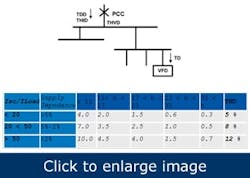
IEEE 519 limits the demand distortion (THDD) and voltage distortion (THVD) at the point of common coupling (PCC). The VFD input current distortion (THID) doesn’t necessarily need to be less than 5% to meet IEEE 519 at the PCC (Figure 1).
Figure 1. IEEE 519-1992 Maximum Harmonic Current Distortion in % of Load
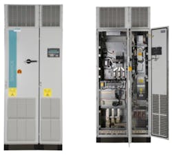
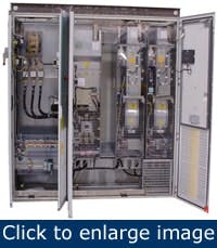
Figure 2a and 2b. 400 hp, 6-pulse drive
Especially in large power distribution systems and installations, in which the variable frequency drive isn’t the main load, six-pulse drives can meet IEEE 519 at the PCC, though sometimes harmonic mitigation is necessary. A range of solutions is currently available for this purpose, including passive and active harmonic filters, typically connected upstream of the VFD, plus drive topologies including multi-pulse rectifiers and active front ends.
On a typical drive, the motor-side inverter controls the motor, the DC link capacitor serves as the voltage source, and the front end charges the DC link. On the standard six-pulse drive, the input line reactor reduces line-side harmonics only by a limited amount, while the higher impedance results in lower harmonics. The THID at the input terminals typically is in the 40% range (Figure 2a and 2b). Let’s now look at three types of newer, low harmonic, variable frequency drives:
- 18-pulse VFD
- Active front-end VFD
- Six-pulse VFD with integral harmonic filter
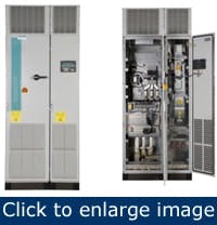
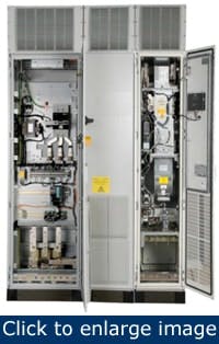
Figure 3. 400 hp, 18-pulse drive with bypass
The 18-pulse VFD is a robust design with a good track record and typically is found in municipal water and waste processing facilities. The typical 18-pulse VFD has a phase-shifting autotransformer with nine-phase output and a high-impedance line reactor. It also includes an 18-pulse rectifier (3 x 6-pulse) as shown in Figure 3. The THID for such a drive typically is 5%, but some manufacturers supply a configuration that achieves a THID of 8%.
For true 18-pulse performance, the transformer secondary voltages and impedances must be identical, while the secondary phase shift must be perfect. If the line supply is connected directly to a single six-pulse bridge, but uses a phase-shifting transformer for the other two, the impedance imbalance results in a greater THID.
The VFD with active front end is fully regenerative, meaning it can feed braking power back into the supply system. It has low harmonic distortion, usually less than 3% THID, operates easily on a weaker power supply having voltage and frequency dips and sags, plus its control of reactive power can even assist in stabilizing a weaker power supply.
{pb}Figure 4. 400 hp, drive with active front end (active infeed)
This type of VFD (Figure 4) has a line-side IGBT converter/rectifier and clean power filter. A line-side rectifier of at least the same current rating as the motor-side inverter provides a controllable power factor of 0.8 lead to 0.8 lag. With a smaller rectifier, the unit can operate at unity PF. The active front end, by definition, is inherently regenerative and can feed power back into the supply system when the motor is braking.
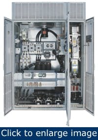
Figure 5. 400 hp drive with integral harmonic filter
The six-pulse VFD with integral harmonic filter is a standard six-pulse drive with the addition of a line harmonic filter integrated into the drive lineup. This configuration provides benefits such as a single enclosure, protection by the drive circuit breaker and fuses. The short-circuit current rating (SCCR) applies to the complete enclosed drive unit, and there’s no need for external protection upstream of the filter. Nor will you need extra power or control cabling for overload or temperature protection. (Figure 5).
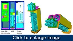
The new line-harmonic filter (LHF) design features a reactor with zig-zag windings (windings from three phases on a common core) to provide some degree of harmonic cancellation. The reactor is combined with a small capacitor bank that results in a compact design, about 16 in. wide for 150 to 400 hp and 24 in. for 500 hp to 800 hp. The THID is approximately 8%, while the PF is unity at full load, capacitive at partial loads, which might present a difficulty on a weak supply network or with small backup generators, less than three or four times the drive rating. The harmonic limits might be exceeded with weak supply systems (Figure 6).
Figure 6. Line side components, LHF and power module shown in CAD
In addition to the compact design, these VFD units typically have a lower cost, higher efficiency and are suitable for safe operation on generator supplies, provided the total drive load is around 25% to 30% of the generator rating, for example, on marine vessels or other remote applications.
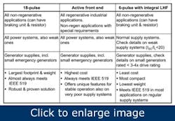
Finally, for direct comparisons, see Table 1.
Table 1. A direct comparison of the options.
Wolfgang Hilmer is product manager, motion control business, at Siemens Industry. Contact him at [email protected].
