How top companies reduce pump failures- and how you can, too
Next to electric motors, centrifugal pumps are the most prevalent modern industrial machines. However, the fact that some U.S. oil refineries, on average, must repair their centrifugal pumps every three years while other refineries enjoy average repair intervals of 10 years is a matter of record. The purpose of this article is to briefly highlight how best-of-class refineries and other petrochemical companies have accomplished such obviously significant failure reductions, and how other pump users can obtain the same results.
Premises and rules
Facilities that reduce failure incidents and rule out certain pump failures accept three well-founded premises and adhere to a few fundamental rules.
Premise No. 1: Repeat failures occur only for one of two possible, fundamental reasons: Either the root cause of the failure hasn’t yet been found, or the root cause is known but remedial action isn’t pursued.
Premise No. 2: Given their simplicity, most pump repair frequencies are excessive. Therefore, many pumps can be improved for reduced failure risk and extended runs, and any repair event presents an opportunity to upgrade and reduce failure risk.
Premise No. 3: Improvements are possible and have been thoroughly documented. Predictive maintenance is valuable; it indicates that a failure will occur unless the user shuts down and repairs the pump. If cost-effective upgrading is feasible and extends component life, one can reduce the frequency and cost of certain predictive maintenance activities. Whenever cost-effective upgrading is feasible and avoids failures, it adds more value than continuing the predictive maintenance cycle.
Parts replacement: Not good enough
Why “doing the same thing we’ve always done” isn’t an acceptable approach is best explained by an example. For the sake of illustration, consider example case 1 — a centrifugal pump that develops a problem. It’s taken to the repair shop and dismantled. The technician finds a defective bearing and replaces it. The pump is reassembled, reinstalled and restarted. The technician might not realize that the failed bearing had been weakened by water in the lube oil. If nothing is being done to exclude water, the repair cycle will simply roll onward and downward.
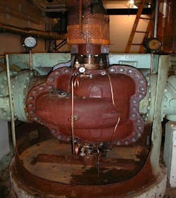
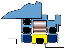
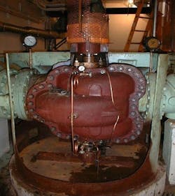
Cost-effective remedial action through upgrading would involve installing a dual-face magnetic bearing housing protector seal (Figure 1), as was done in a municipal water pump (Figure 2). Before this modification, bearings had lasted only about two months. With the seals, the bearings have been in service for more than two years and exhibit no sign of distress.
Figure 1: Dual-Face Magnetic Bearing Housing Seal (Source: AESSEAL plc, Rotherham/UK, and Knoxville/Tennessee)
Figure 2: Vertically-oriented Axially Split Centrifugal Pump in Municipal Water Service. Installing a Dual-Face Magnetic Bearing Housing Seal Prevented Future Water Contamination (Source: AESSEAL plc, Rotherham/UK, and Knoxville/Tennessee)
Structured failure analysis
There are literally hundreds of examples of a properly structured root-cause failure analysis and upgrade program yielding immediate and measurable payback. Fortunately, such programs are deceptively simple and quickly implemented by anyone who wishes to do so. We call it the FRETT approach because it recognizes that, without exception, the basic agents of machinery component and part failure mechanisms are always force, reactive environment, time or temperature1. These basic failure mechanism agents may combine to hasten component degradation.
Isolate the basic agents involved through a process of elimination. Start by thoroughly examining the failed part and determining from its appearance whether the damage occurred while the pump was operating or while standing still. Suppose the technician had observed corrosion on the bearing. If it had occurred in operation, the corrosion would be uniform. Non-uniform corrosion would suggest that it had happened at standstill.
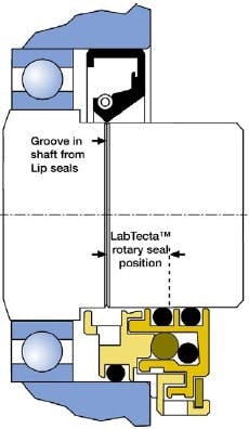
In any event, keeping water away from the bearing is a sound remedy. Magnetic bearing housing protector seals are ideal for the flooded lubrication in vertical pumps. Non-contacting labyrinth seals, not lip seals, (Figure 3) are best for the majority of horizontal centrifugal pumps.
Shaft-Contacting Lip Seal, Top, vs. Non-Contacting Dynamic O-Ring Seal, Bottom. (Source: AESSEAL, plc, Rotherham/UK and Knoxville, Tennessee)
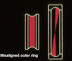
Consider a case in which an unduly hot or noisy bearing exhibited the load pattern shown in Figure 4. From understanding the published load-speed-life relationship and knowing that failure had occurred after a relatively short time, one might easily rule out the first “T” ingredient — time. Absent evidence of discoloration and carbon formation, one could rule out the second “T” — temperature. If no corrosion was evident, a reactive environment could be ruled out. You’d be left to pursue “F” — force. A continuous wear pattern rules out installation damage from hammer blows.
Figure 4: Skewed Load Pattern Is a Sign of Non-Concentric Bearing Components
Nevertheless, contributing or interacting factors also are part of a system. Consequently, you’ll need to subject the entire system to review and scrutiny. In other words, a failed bearing might exhibit the tell-tale sign of continuous force application in the form of a skewed load pattern (Figure 4). This skewing would overload a corner of the outer race, constituting an out-of-range force. Investigating the plant’s installation practices might uncover this out-of-range force to have been caused by poorly aligned piping that was field-fitted by forcing it into place. Indeed, brute-force pipefitting often distorts pump casings to the extent that bearing components are no longer concentric. A change in installation practices might cure the problem, whereas buying stronger bearings, stiffer baseplates and superior lubricants, at best, will only address the symptoms.
A third example deals with mechanical seal failures in pumps (Figure 5). Again, thoroughly examine the defective component and eliminate any of the four ingredients (FRETT) that aren’t involved in the failure.
Figure 5: Mechanical Seals Failed Due to “FRETT”
Mechanical seal manufacturers furnish checklists that link symptoms to causes. So, if a seal elastomer O-ring feels gummy, the checklist is likely to link that form of degradation to a reactive environment. Your remedy is either finding a compatible O-ring material or isolating the O-ring from the reactive environment with a multiple seal arrangement and barrier fluid. Sometimes, such changes made to an entire system are appropriate and a thorough comparison of vendor experience will point out different options.
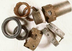
The fourth example involves slinger rings (Figure 6). Also called oil rings, slinger rings represent one of the least expensive means of applying lube oil to bearings. From about 1840 until 1990, slinger rings were fabricated from brass or bronze. More recently, some manufacturers are experimenting with plastic and aluminum rings. The results are mixed, at best. In any event, oil rings suffer from a number of limitations that equipment suppliers and users don’t always recognize. Reliability-focused plants avoid oil rings wherever their use represents an avoidable risk; tracking the bearing temperature and observing oil discoloration will usually indicate ring degradation.
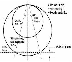
Figure 6: Traditional slinger rings are sensitive to depth of immersion, oil viscosity,
shaft horizontality, ring eccentricity and bore finish (surface roughness)
Shaft alignment tools only ensure that shafts are coaxial. Even the best laser-optic shaft alignment system can’t ensure that your shaft centerlines are absolutely horizontal. An oil ring on a non-horizontal shaft will run downhill until it encounters frictional contact with either a groove machined in the shaft or the inside of the bearing housing. The oil ring now slows, feeding less oil into the bearing. Many observers also have seen oil rings that showed evidence of edge wear and metal loss. Needless to say, the metal shavings contaminate the lubricant — not a desirable condition by any measure.
Oil ring movement and circumferential speed also are affected by immersion in the lubricant and lubricant viscosity. Typical immersions are shown in Figure 6, but recommendations might vary by pump sizes. Quite obviously, a more deeply immersed oil ring, or oil rings contacting an excessively viscous lubricant, won’t perform as intended. Also, for good tracking and consistent motion, oil rings must be concentric within 0.002 in. (0.05 mm).
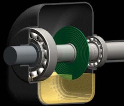
Instead of reinstalling new slinger rings in a bearing housing where “T” (temperature) and “RE” (ring wear debris) have gone out of range, reliability-focused users will upgrade to flinger discs (Figure 7). Because flinger discs are secured to the shaft, they aren’t subject to the compounded influences of horizontality, viscosity, immersion and concentricity. They’re a vast improvement over oil rings and are available in many domestic and European pump models.
Figure 7: Viton Elastomer Flinger Disc That Avoids The Problems Incurred With Slinger Rings (Source: TRICO Mfg. Corporation, Pewaukee, Wisconsin, www.Tricomfg.com)
Reference 2 contains a page from a 1960s-vintage catalog page issued by a then-prominent U.S. pump manufacturer. The page shows the flinger discs furnished with its pumps and states, rather pointedly, “anti-friction oil thrower ensures positive lubrication and eliminates the problems associated with oil rings.”
Focus your efforts
You can do much to reduce your risk of equipment failure. Well-developed specifications, drawing and document reviews, compliance with uncompromising installation procedures, appropriate operator and mechanical workforce training, and a good combination of preventive and predictive maintenance (periodic condition monitoring) are just a few of the proven ways that come to mind.
When failures occur, there’s no substitute for proper, repeatable approaches to failure analysis and troubleshooting. Develop checklists. Apply the systems approach. Collect data before trying to determine what happened. But your most productive measure is to remember FRETT, the four basic agents of component distress. Use a process of elimination to focus on the most probable agents, or perhaps those that can be screened easily and rapidly. The final and most important effect-versus-cause comparison will then almost naturally point to the one area that contains the root cause of a failure event.
While the old-style focus on repair often results in burdensome and avoidable pump failures, this systematic root-cause failure analysis and prevention of repeat failures can pay major dividends. Accepting the initial premises helps identify much low-hanging, ripe fruit, which should be harvested first. Your pump maintenance cost reduction program will succeed if you:
- Understand that equipment vendors base machinery operation judgment and component choices on near-perfect conditions, and field conditions are rarely ideal.
- Accept the facts that cost-effective upgrades are possible and that engineers and technicians at your plant must become familiar with them.
- Consistently implement such basic upgrades as have been explained above.
- Insist on root-cause failure identification using the FRETT method.
- Refuse to concede that repeat failures are unavoidable.
References:
- Bloch, Heinz P.; “Root Cause Analysis of Five Costly Centrifugal Pump Failures”. Proceedings of the 7th International Pump Users Symposium, Houston, Texas, 1990
- Bloch, Heinz P., and Allan Budris; “Pump User’s Handbook—Life Extension,” 2nd Edition (2006) Fairmont Publishing Company, Lilburn, Georgia 30047, ISBN 0-88173-517-5
- Bloch, Heinz P., and Geitner, F.K.; “Machinery Failure Analysis and Troubleshooting,” 3rd Edition (1998) Gulf Publishing Company, Houston, Texas 77252, ISBN 0-88415-662-1
Heinz P. Bloch, P.E., retired as Exxon Chemical’s regional machinery specialist for the United States and now lives in Des Moines, Iowa. Contact him at [email protected] and (515) 225-0668.
