Pumps are used in HVAC applications to circulate water for heating and cooling purposes. As long as theres a need for hot or chilled water to satisfy the interior environmental conditions, pumps are running; as such, pumps are large consumers of electrical energy in a heating and cooling plant. Thats why you should explore various flow pumping strategies that might be applied to new systems, as well as those that might be adaptable to existing hydronic systems. These strategies can save energy and operating costs while increasing the controllability of a plant.
The pumps role
To provide the design flow rate, which is a function of both the design load and desired temperature difference between the return line and the supply line, the pump must be capable of operating against the greatest resistance to flow (pressure drop) in the system.
The greatest resistance, also called the hydraulically most remote point, is a function of the piping network, pipe sizes and flow rate to and from the most remote point. Its not necessarily the geographically most remote point, though. As long as the pump can maintain the required flow at the hydraulically most remote point, it will maintain flow at areas of less resistance (lower pressure drop). The power required to push water throughout the piping network is proportional to flow rate and pressure difference. Some useful hydronic formulas are presented in the sidebar.
Constant volume primary systems
Many older or smaller-capacity hydronic systems, either chilled water or hot water, use a two-pipe (supply and return) primary pumping system similar to that shown in Figure 1. The pump maintains a constant flow rate throughout the system and three-way bypass valves allow flow to vary through the load while maintaining constant flow through the branch. The required, or peak design, flow rate is therefore pumped continuously during periods when heating or cooling are needed.
Figure 1. A typical two-pipe primary pumping system continuously circulates water at full flow. (Click to enlarge)
But, neither heating nor cooling loads are constant. They vary with, among other things, occupancy, equipment usage and changes in the external environment. Bypass valve modulation provides for proper response to the varying load. However, some of the supply water flows directly into the return line to accommodate the varying load. This results in the return water temperature being brought closer to the supply water temperature or a reduction in the temperature difference (delta-T).
As the temperature difference decreases, the load on the boiler (or chiller or heat exchanger) is reduced, which causes it either to unload or shut down. The design, or full load, temperature difference across the boiler (or chiller) must be equal to the design temperature difference across each load for this type of system.
Primary-secondary pumping
Bell and Gossett pioneered the development of primary-secondary pumping in the mid-1950s. This arrangements original intent was to increase the allowable system design temperature difference, thereby reducing system design flow rates (Sidebar, Eqn 1) with the resulting decrease in pump horsepower without sacrificing system controllability. The basic operation of the primary-secondary arrangement is predicated on a fairly simple premise:
When two piping circuits are interconnected, flow in one causes flow in the other, to a degree depending upon the pressure drop (resistance to flow) in the piping common to both. (1)
This premise is illustrated by the mono-flow circuit shown in Figure 2. The valves provide a fixed resistance (pressure drop) in the main circuit, which induces flow into the load circuit. This equalizes the pressure drop between the two valves, regardless of whether the water flows through the load circuit or the common piping.
Figure 2. In the mono-flow circuit, the valve position induces flow in the load circuit. (Click to enlarge)
If the valves were removed and the pressure drop in the common piping reduced to practically zero by adjusting the locations of the load circuit connections on the main circuit, practically no flow would be induced into the load circuit (Figure 3). The arrangement wouldnt be very good at providing flow to a load, as the pressure difference in the common piping is negligible, the flow in the secondary loop also would be negligible.
Figure 3. This arrangement doesnt provide flow to a load. (Click to enlarge)
However, a pump installed in the secondary circuit establishes flow (Figure 4). This secondary pump is selected to provide the design flow rate to the load in the secondary loop at the pressure drop through the secondary loop. Because the pressure drop in the common piping is negligible, it wont affect the secondary pump. Therefore, the secondary pump can be selected independently of the primary loop. Similarly, the secondary loop will have a negligible affect on the primary loop.
Figure 4. A pump installed in the secondary circuit ensures flow to a load. (Click to enlarge)
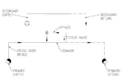
Now, the two loops can be considered in isolation, and a large system could be designed as a series of smaller secondary systems connected to a primary loop (Figure 5). The primary loop provides heat (or cooling) while the secondary loops act as distributors.
Figure 5. A large system could be designed as smaller secondary systems connected to a primary loop. (Click to enlarge)
The pipe connecting the primary supply line to the primary return pipe is known as a cross-over bridge. The pressure difference (head) the primary pump must overcome is the hydraulically most removed cross-over bridge. As the primary pump is no longer required to pump through the load, its head is reduced. Referencing Eqn 2 and 3 in the sidebar, a reduction in head provides a reduction in horsepower at the primary pump. Although the secondary pumps horsepower requirements will be at least equal to the reduction in horsepower at the primary pump, there will be an overall energy savings as the secondary pumps cycle to meet load conditions.
Variable secondary temperature
The discussion so far is based on equal delta-T in both the primary and secondary loops. Allowing the temperature difference in the secondary loop to increase can yield additional energy savings. An increase in design temperature difference allows a reduction in design flow rate (Eqn 1). A reduction in flow results in a horsepower savings as well as installation savings as smaller piping and valves could be used.
In the variable secondary temperature application, the primary flow will be greater than the secondary flow and both flow rates would be constant. Figure 6 shows the basic arrangement.
Figure 6. In a variable secondary temperature application, a constant primary flow exceeds the constant secondary flow. (Click to enlarge)
The flow rate through the cross-over bridge is based on the secondary loop heating (or cooling) load and the primary loop temperature difference. The flow through the secondary loop is based on the same load, but the desired delta-T in the secondary loop must be equal to or greater than the delta-T in the primary loop.
As the load decreases, the valve modulates to reduce the flow from the primary loop into the secondary loop (increasing the bypass flow). This causes the secondary supply temperature to drop (in heating) or rise (in cooling), thereby reducing the capacity of the heat transfer. An increase in load has the opposite effect.
The valve modulation enhances load controllability. As heat transfer rates are adjusted to match loads instead of merely cycling the secondary pumps on and off or, in the case of a primary only system, cycling the boiler or chiller.
The arrangement also could be used in a system with multiple supply water temperature requirements. For example, consider a primary loop designed for a constant temperature of 200°F. Connected to the primary loop are an air handling unit coil requiring 200°F, circuits of baseboard radiation requiring 180°F and a radiant floor requiring 120°F. In this case, each valve would be controlled by a temperature sensor in its secondary supply line to maintain its temperature.
Variable secondary flow
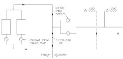
In variable secondary flow arrangements, the primary loop still operates at constant flow. The secondary pump(s) adjust their speed to change the flow rate in response to load changes. A variable-frequency drive modulates the electrical output to the pump motor in response to load changes that usually are sensed by a pressure transmitter mounted in the hydraulically most remote point in the secondary loop.
This piping arrangement introduces the concept of a decoupling loop, similar in application and intent of the common pipe in constant-flow primary-secondary systems. The decoupling line gives the excess flow a place to go.
In constant-flow applications, the primary flow is designed to be greater than the secondary flow. In contrast, in a variable-flow loop, there are occasions when the secondary flow exceeds the primary flow, particularly in plants with multiple staged primary and secondary pumps. The reason for this phenomenon is discussed below.
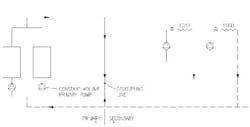
Two basic pumping concepts are associated with variable-flow secondary systems. One, depicted in Figure 7, uses central secondary pumps. The second, shown in Figure 8, uses distributed pumping. The loads depicted in these figures could be anything from air handling units to entire buildings. The operation of this type of system allows the secondary flow rate to match the load requirements while maintaining constant flow through the boilers or chillers.
Figure 7. The decoupling line accommodates flow differences between the primary and secondary loops in a variable flow secondary system. (Click to enlarge)
Figure 8. A variable flow secondary system using distributed pumping is controlled by valve modulation at the individual loads. (Click to enlarge)
As the load increases, two-way valves in the system open. This causes a reduction in differential pressure at the hydraulically most remote point. The pressure transmitter mounted there causes the VFD to increase speed, and therefore flow rate, to raise the differential pressure. If there are multiple pumps available, and the operating pump(s) is at maximum speed, the signal starts the next pump. Similarly, as loads decrease, valves close to increase the differential pressure resulting in decreasing pump speed. Varying the flow to meet load requirements saves pump horsepower and, therefore, energy costs. Maintaining constant secondary supply temperature enhances controllability.
Decoupling line
This discussion is based on the central secondary pumping system shown in Figure 7. The principle is similar to that for the distributed system. Consider that the primary pumping is using two pumps, each of 100-gpm capacity, and the secondary pumps also are of 100-gpm capacity. At full load, the plant produces 200 gpm.
Now, assume a moderate day in spring, when the load in the secondary loop requires 50 gpm. One secondary pump is operating at 50% of capacity while one primary pump (constant speed) is pushing 100 gpm. The excess flow in the primary loop flows through the decoupling line and into the return line to the suction side of the primary pump. The two water flows mix where the decoupling line connects to the return line.
This mixing of the excess primary water, having zero delta-T, and the secondary return water, with design delta-T, results in a primary return water delta-T that is less than the design value. As the boiler or chiller attempts to maintain a constant primary supply temperature, its firing rate or compressor circuits change accordingly.
As the load increases, the secondary pump speeds up. When it reaches full speed, the flows in the primary loop and the secondary loop are balanced; theres no flow in the decoupling line. A further increase in load causes the next secondary pump to start. The reaction to the load increase is more immediate here than on the primary side because the supply temperature controls the primary side. As the two operating secondary pumps now provide more than the 100 gpm flowing in the primary loop, flow in the decoupling line reverses from the secondary return toward the suction side of the secondary pump.
The immediate effect is that mixing the secondary return with the primary supply water causes a lower (hot water) or a higher (chilled water) secondary supply temperature.
This other-than-design temperature results in a higher than design delta-T in the primary loop, which will, in turn, cause the second boiler or chiller and its primary pump to come on line, thereby reversing the flow in the decoupling line.
Primary-secondary pumping has been in use since the mid-1950s, yet many older and smaller systems havent taken advantage of this application. The systems highlighted here can provide energy incentives centering on lower pump use or pump horsepower; increased controllability by matching flow rate and temperatures to the load; and on new applications, lower installed piping costs by taking advantage of larger secondary side temperature differences.
Useful hydronic formulas
Q = 500 x TD x q (Eqn 1)
WHP = (q x P) / 3960 (Eqn 2)
BHP = WHP/Ep (Eqn 3)
Where
Q = Heating or cooling load, BTU/hr
TD = Temperature difference between the supply and return lines, °F
q = Water flow rate, GPM
WHP = Water horsepower (theoretical power required)
P = System resistance to flow (pressure drop; head), ft. w.c.
BHP = Brake horsepower (actual power required including pump efficiency)
Ep = Pump efficiency
References:
(1) Primary secondary pumping application manual; Bulletin No. THE-775; ITT Fluid Handling Training & Education Dept; 1968
(2) 2004 ASHRAE Handbook HVAC Systems and Equipment
(3) HVAC Design Criteria, Options, Selection; 2nd Edition; William H. Rowe III, AIA, PE; 1994 RS Means Company Inc.
Robert J. Flaherty, P.E., LEED AP is a Principal at SEi Companies, Boston. He may be reached at [email protected]


