In brief:
- Lip seal reliability is a function of the shaft’s surface geometry and the seal’s material of construction.
- The preload the lip seal exerts on the shaft is a critical variable.
- There are six relevant factors that you should use when selecting a shaft seal.
Shaft seals on pumps, compressors, turbines, and other rotating equipment not only retain the bearing lubricants but also protect them from external contaminants. Both contact lip seals and non-contact bearing isolators can serve this purpose. The best solution for a given application depends largely on service conditions, desired performance, and value, or cost plus delivered performance.
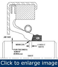
Figure 1. A seal should be riding on thin meniscus of oil.
Contact lip seals are available in a variety of materials, sizes, and configurations. Made of elastomers molded into engineered angles and contours, these seals act as micro-hydrodynamic wedges that raise the lip and recirculate lubricant to form a thin meniscus of oil on which the seal rides. This hydrodynamic action reduces friction between the lip and shaft (Figure 1).
There are three basic types of lip seals. General-service seals, using snap-in springs to provide lip load, are made of commodity-grade elastomers that offer satisfactory performance at lower speeds and have the ability to accommodate misalignment. High-performance lip seals are made of specially engineered synthetic rubber and incorporate molded-in springs for improved performance and service life. Specialty lip seals have custom-engineered designs for pressurized, non-lubricated, and other demanding conditions.
As contact lip seal technology evolves, new materials, geometries, and configurations are being tested for their ability to reduce or overcome frictional drag between the lip and the shaft. Because the hydrodynamic pumping action isn’t continuous, the lip can come in contact with the shaft, especially during dry-running startup. Dry running increases drag (the force needed to overcome it), and the power required to turn the shaft.
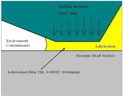
Figure 2. Close-up view of seal lip-to-shaft interface.
Direct contact also causes grooving on the shaft and wear on the lip. Repairing damaged shafts is costly and time-consuming, so most contact lip seal manufacturers recommend ranges for shaft hardness and surface finish. Formation of the oil meniscus is subject to a combination of factors, but mostly radial load, which is the sum of the forces the lip exerts on the shaft (Figure 2).
The greater the load on the lip, the harder it is for the oil to lift it; too little load and the oil will leak past the lip, too much might result in higher power consumption and premature lip wear. Among other factors, radial load is a function of lip material and geometry, the type of spring used, and seal interference. The angle of the lip and location of the spring play a critical role in seal design. Interference is built into the lip design to develop preload on the shaft and provide greater misalignment tolerance. Excessive pre-load, however, can cause shaft grooving and make a seal difficult to install. Harder elastomers such as hydrogenated nitrile butadiene rubber (HNBR) are more abrasion-resistant, but can generate too much lip load thereby causing the seal to generate excessive heat.
Contact lip seal performance depends upon a proper match with the application’s requirements. A number of factors affect seal performance, and taking them into account helps ensure selecting the optimal seal in terms of reliability, longevity, and maintenance.
It’s critical to know how a seal is going to be used, whether its primary function is to retain lubricants, prevent ingress of contaminants, or both. If intended solely for lubricant retention, the lip should be directed towards the lubricant. If the purpose is to exclude contamination, it should point towards the contamination and away from the lubrication. In applications that require both, either a dual-lip seal or two single-lip seals placed back to back might be used.
Non-contact seals
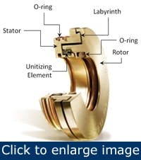
Figure 3. These are the basic components of a bearing isolator.
The media to which the seal will be exposed also might determine the type selected. Dry-running applications might require bearing isolators rather than contact lip seals, which need lubrication to prevent premature wear. Standard bearing isolators also can be used in oil mist or splash applications in which the lubricant surface is below that of the seal. Unlike lip seals, isolator seals are a non-contact means of retaining lubricants and excluding contaminants. Standard labyrinth type seals are characterized by close tolerances and intricate, circuitous paths with abrupt directional changes to prevent leakage (Figure 3).
Bearing isolators also are more energy-efficient than contact lip seals. With minimal dynamic contact, they present little to no frictional drag. As a result, they reduce power consumption by as much as 99% and can last 65 times longer than lip seals (Figure 4). The power savings from a single seal might not be particularly impressive, but it becomes significant when multiplied by the hundreds of pieces of rotating equipment in a typical processing plant.
Figure 4. Test results show the power consumption of lip seals and bearing isolators tested on a 3-hp motor.
Application data
A simple acronym, STAMPS, provides a guide to selecting the correct seal for an application. The input needed for the STAMPS concept includes size (shaft, housing bore, and available bore depth), temperature (continuous/maximum), application variables (equipment, constant or intermittent rotation, shaft misalignment with housing bore, dynamic run-out), media (type and level of lubrication), pressure (continuous/maximum), and shaft surface speed (continuous/maximum).
[pullquote]The size and surface finish, particularly the shaft, can affect lip seal performance. It’s important to achieve the correct amount of interference for proper sealing. Too much results in premature wear; not enough prevents the sealing element from following shaft irregularities, causing it to leak. The shaft and bore should fit within the recommended tolerance for the seal being considered. Because the shaft and the sealing element form the primary sealing system, it’s important that the shaft surface finish be within the proper range.
A shaft finish that is too rough can cause leakage. Conversely, if the surface finish is too smooth, the sealing element won’t be able to form a lubricating film (meniscus), thereby resulting in premature lip degradation. Most seal manufacturers suggest plunge grinding rather than machining, which can form small screw-like trenches that pump lubricant out of the seal and might produce a direct leak path. In addition, shaft and bore chamfers should be machined to prevent damage during installation.
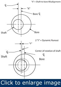
Figure 5. This illustration shows shaft-to-bore misalignment and dynamic run-out geometry.
If these factors are within the seal manufacturer’s specifications, shaft rotation will produce the hydrodynamic action as microasperities on the lip act as small viscous pumps displacing lubrication in a steady direction.
Operating temperatures also can affect seal performance. The maximum temperature to which the seal will be exposed should be known to select the correct elastomer material. In oil-lubricated applications, add 50oF to the maximum process temperature to account for frictional heat at the lip. For limited grease-lubrication, add 100oF. A sealing element exposed to temperatures beyond its material rating might harden or crack, resulting in leakage through the cracks themselves or because the hardened material can no longer conform to the shaft surface.
Other application variables include misalignment and runout conditions. Shaft-to-bore misalignment is a static condition whereby the shaft is off-center relative to the bore. Run-out is a dynamic misalignment condition in which the shaft doesn’t rotate about its true center (Figure 5)
Excessive misalignment can cause uneven wear and reduce seal life. The degree of misalignment becomes increasingly important as shaft surface speed increases. Most seals can accommodate as much as 0.015 in. of misalignment, but some can accommodate as much as 0.125 in. Seals with high misalignment capabilities are designed to conform to shaft eccentricities without leakage or damage to the seal.
Lubrication conditions also might determine the type of seal that’s selected. Dry-running applications might require labyrinth technology (bearing isolators) instead of contact lip seals, which need lubrication to prevent premature lip wear. Table 1 summarizes the differences between lip seals and isolators.
| Variable | Contact lip seals | Bearing isolators |
| Temperature | -40 °F to 400 °F (depending on elastomer) | 22 °F to 400 °F (depending on O-ring material) |
| Equipment | Rotating (constant/intermittent) | Rotating (constant/ intermittent) |
| Fluids | Determines elastomer used, specific information needed | Accommodates broad range of media, check compatibility of O-ring material |
| Pressure | 3 psig to 7 psig (depending on shaft speed) | None; oil sump needs to be vented |
| Shaft | = Rockwell C 30-40 hardness, 10-20 micro-inch Ra with no machine lead; plunge grinding required, no surface defects | 64 micro-inch or smoother for O-ring contact |
| Dry running | Not recommended; seal will wear, damage shaft, and fail | Can run dry |
| Lubrication level | Minimum: Splash lubrication Maximum: Oil level above seal |
At or below bottom of the seal |
| Dynamic shaft run-out/shaft-to-bore misalignment | 0.015 in. total, some good to 0.125 in. total, speed dependent | 0.020 in. total, axial up to 0.025 in. total |
| Shaft surface speed | 1,000 fpm to 7,000 fpm (depending on elastomer and seal design), high-speed applications require frequent replacement because of wear | PTFE: to 4,500 fpm, metal: to 12,000 fpm |
Table 1. This listing provides a capsule view of the differences between lip seals and bearing isolators. |
||
In addition to lubricants, lip seals might come into contact with other chemicals with which they must be compatible to prevent attack, degradation, and leakage. If the application includes external contaminants, a dual-lip seal might be more effective than a single-lip seal.
Application pressure could be critical because most oil seals are rated at 3 psig to 7 psig, depending on shaft speed. Pressure capability is inversely related to shaft speed - as the speed increases, the pressure rating decreases. High-pressure seals are available, but if exposed to higher than specified pressures, can leak or blow out from the bore housing, posing a significant safety concern.
Different seals types have varying speed ratings. The shaft surface speed can be calculated easily if the shaft size and rpm are known. If surface speed exceeds seal specifications, the temperature at the lip will increase, possibly causing premature degradation, especially under limited lubrication conditions.
In addition to the above variables, take into account the performance of the seal being replaced and expectations for the new seal. If the current seal is deemed unsatisfactory, there’s little point in replacing it with the same thing. If it leaks, it’s helpful to know where and how much. If it shows signs of thermal or chemical degradation, a different seal material might be called for. Application pressure exceeding that for which the seal is rated might require a different type of seal.
A split seal might be the answer if a quick fix or ease of installation is the objective. Dirty, dusty environments such as those encountered in steel mills might call for seals with secondary lips. A bearing isolator or more abrasion-resistant seal might be specified to reduce maintenance and unscheduled downtime.
And, of course, cost always is a consideration. Taking these factors into account, particularly the quantitative STAMP data, can help ensure the seal selected will meet or exceed users’ expectations.
Karyn Caverly is an applications engineer at Garlock Sealing Technologies. Contact her at [email protected] and (315) 597-7258.
