Real-time machinery evaluation leads to plant profitability
Performance evaluation of rotating machinery in a refinery can provide many benefits to the plant engineering and reliability team. This case study deals with pumps; however, such an exercise can be applied equally to other major and critical pieces of machinery available in an operating plant. Centrifugal compressor monitoring can be done using such an approach to evaluate the operating context of the compressor. Variables such as the operating margin around the anti-surge line, compressor polytropic head and efficiency, and gas horsepower can be readily determined in real time giving valuable information on the condition of a particular asset. This approach also helps in cutting back heavy reliance on the OEM and utilizing on-site, in-house expertise in trying to diagnose and predict complex rotating equipment issues.
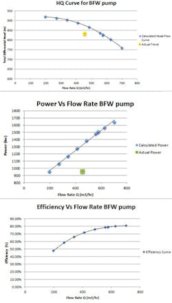
You can develop a head-flow Excel graph similar to Figure 1. You can color-code the preferable and the allowed operating regions from the best efficiency point (BEF) as per API 610 requirements on the pump curve. The real-time data point can then be imported into Excel and subsequently shown on the graph as described in the study giving a good and easy visual of where a particular pump is operating relative to the pump curve. Pumps operating beyond the allowable margin can be addressed at the soonest available interval. Pumps in the allowable margin can be studied further and related with their overall vibration limits and seal reliability, and an effort can be made to operate such pumps in the preferred region.
Many machinery vendors have developed sophisticated programs to monitor the real-time performance of machinery. These packages and solutions can often be expensive and cumbersome to implement in some cases. This case study provides a simpler means to evaluate machinery performance. Depending on the complexity required, many basic and even advanced calculations can be done within Microsoft Excel, provided sufficient and important data can be extracted from the real-time plant data historian.
Deciphering data
Evaluating machinery condition forms the cornerstone of predictive maintenance (PdM) programs in many operating plants. Organizations planning to implement reliability-centered maintenance programs or maintain an existing program are bound to benefit highly with such tools and exercises in performance evaluations. These provide a cost-effective way to analyze machinery without heavy capital investment on sophisticated programs and subsequent training. Maintaining this information on a local server database in the plant can assist the operating personnel in understanding how they are operating the machinery and what impact on reliability, if any, such an operation produces in the long term.
In contrast, data mined from sophisticated monitoring software often requires specialized expertise to decipher and relate it to the operating context. Such detailed data is often very useful in performing detailed root cause analysis in repeated or critical machinery failures.
Experience has also shown that presenting cost savings or breakdown information to senior management is a good way to capture their attention and address key issues in the plant. This case study does this by utilizing pump operation and efficiency to capture energy waste and subsequent lost revenue in operating costs. Use this process and improvise the presentable data in a way meaningful to drive change in your organization. When developing such evaluation sheets, it’s a good practice to include the process operating variables so that a trend and a relationship can be drawn between upset process conditions and machinery response. This data is very valuable during RCA discussions and investigations.
Keeping the evaluation process simple and concise by filtering unwanted data and presenting the key data can help a practicing engineer avoid the old adage of paralysis through analysis.
It’s a fact that, if you can’t measure something, then it’s quite difficult to control that something. We focus our attention on the centrifugal pump, one of the most common pieces of rotating machinery in an oil refinery. A poorly operating centrifugal pump in a refinery can lead to high maintenance and operating costs due to poor efficiency.
Measurement with reference
Performance evaluation of any machinery including centrifugal pumps begins with the original vendor-supplied data. This data includes original performance curves, operating conditions, power and efficiency curves as calculated by the OEM, and various other important bits of information pertaining to the equipment. This forms the benchmark from where the condition of any machinery including our centrifugal pump can be ascertained.
The second most important prerequisite is to have the right plant monitoring system. These days many medium- to large-scale operating plants including petrochemical and oil and gas refineries use state-of-the-art process monitoring systems. These systems are capable of showing real-time information and are often capable of trending, managing, and monitoring complex plant processes. Additionally, such systems are often user-friendly and can be customized with visual basic programming or other languages to interface with external applications such as Microsoft Excel or Office applications to present and evaluate the available data in a meaningful and productive fashion. We leverage one such system called PI Process Book developed by OSIsoft along with Excel to capture, trend, and evaluate key information about the centrifugal pump and present the advantage of real-time performance monitoring of all critical machinery.
Boiler feed water (BFW) pumps are critical pumps that supply feed water to the boiler systems that in turn produce steam for the entire plant. This steam is used in various process operations, in heating, and in running critical turbomachinery including both small and large steam turbines throughout the plant. BFW pumps are also used in processes involving oil recovery via underground steam injection through steam-assisted gravity drainage (SAGD) applications. Evaluating these pumps proactively helps avoid unnecessary operational interruptions and shutdowns, which in turn helps to save costs and increase uptime and profitability.
Step 1: Develop the excel sheet with all the relevant performance data for the pump (Table 1).
Table 1. Head, flow, power, and efficiency test data for BFW pump.
Step 2: Generate the appropriate graphs in excel required to monitor the performance of the pump (Figure 1).
Figure 1. Generate the appropriate graphs in excel required to monitor the performance of the pump.
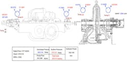
Step3: Use the plant monitoring system, in this case PI ProcessBook, to capture and develop all process tags available in the database giving all information about particular machinery, in our case the BFW pump.
Figure 2. This BFW screen from ProcessBook shows the pump turbine layout and tags.
Figure 2 is a snapshot developed in ProcessBook for the BFW pump that’s being run by a steam turbine. Capture all the important tags that are relevant to a particular piece of equipment — in this case, X,Y vibration readings, suction, discharge pressure, flow, bearing temperature, and speed for the BFW pump. These tags are capturing and presenting real-time process and vibration information as the pump is operating.
Many of the tags used in software such as ProcessBook or other process monitoring plant software can be called into the Microsoft Office package in real time for detailed data analysis. Flow, suction pressure, discharge pressure, calculated total dynamic head (TDH), and hydraulic power for the pump were imported into Excel as shown in Table 2 for analysis and monitoring of the pump.
Table 2. Process and calculated data for BFW pump.
Step 4: Utilizing Excel sheets by integrating real-time process data to analyze, monitor, and take corrective action when necessary helps to increase uptime and save operating costs.
Additional Resources
|
This crucial step integrates all the available information to efficiently monitor the equipment. Figure 1 shows the H-Q and power curves. These curves have been incorporated with real-time information showing the pump TDH flow and pump hydraulic power, respectively. This helps to present the real-time pump operation relative to the actual operation of the pump during performance test at the test bed after manufacturing. Visual presentation of this information helps to understand how far the pump has moved away from the actual operating point during normal plant operation. It also helps to estimate operating power losses as a result of drop in pump operating efficiency.
Efficiency of a centrifugal pump is simply defined as the ratio of the amount of power we get out of the pump to the amount of power we put into the pump. It is easy to see pumps operating away from the BEP aren’t being utilized correctly in an operating plant. There are various causes leading to such operation. They include:
- internal wear of running mechanical components leading to re-circulation
- issues with pump bearings leading to high preload or over-lubrication
- running pumps with throttled discharge valves
- incorrect pump selection for the application.
Magnitude of costs involved
To better understand the magnitude of costs involved in running an inefficient pump, we look at the lifecycle cost (LCC) of the pump.
Equation 1: LCC =Cic +Cin +Ce +Co +Cm +Cs +Cenv +Cd
Cic = initial costs, purchase price (pump, system, pipe, auxiliary services)
Cin = installation and commissioning cost
Ce = energy costs (predicted cost of operating the system including driver)
Co = operation costs (labor cost of normal system supervision)
Cm = maintenance and repair costs (routine and predicted repairs)
Cs = downtime costs (loss of production)
Cenv = environmental costs
Cd = decommissioning/disposal costs
Cost of energy (Ce) consumption will usually dominate the equation, and therefore it’s critical to maintain and run pumps efficiently. Assume that the BFW pump discussed above is being run on a motor, as opposed to a turbine, to help our assumption of using a cost of $0.07495/kWh.
Equation 2:
Equation 3:
Using a modified version of Equation 3 in the ProcessBook calculation, the hydraulic power of the pump was computed using the vendor curve in Figure 1 on what the OEM proposed the shaft power for a given flow would have been for a new pump. It was determined that the pump was operating at an efficiency of 0.74. Now assuming a motor efficiency of 0.80, the power required for the system would be calculated in Equation 4:
Equation 4 gives a power input requirement of 1,612 kW for this pump and the assumed motor. Assume $ 0.07495/kWh for energy cost and, if this system were running throughout the year, 8,765 hours. The total approximated energy cost of running this pump would be $1,059,427. This gives an idea of how important it is to operate pumps close to their BEP and to monitor the condition of the pump proactively to ensure it doesn’t waste excessive energy. The process of calculating the energy cost at different operating points based on the efficiency of the pump can be automated in Excel. It’s quite evident seeing how this cost would add up for multiple pumps and other turbomachinery in an operating plant. Time averaging of the input power would provide a more concise estimate of energy cost associated for a given machine.
Conclusion
It would be beneficial to develop such sheets for all plant machinery, integrating process data and storing them in a common database to give a good measure of equipment performance and subsequent impact on the energy costs. A proactive approach such as this will most definitely impact the bottom line of an operating plant, in terms of safety and cost, in a positive manner.


