The hazards
Electrical measurements require the system to be energized. The meter and test leads are connected to a source of considerable energy, and mistakes can have disastrous consequences. The more serious hazards include:
- Electrocution from contact with exposed live connections at the test probes or plugs.
- Arcing when a dislodged test lead comes in contact with a conductive object.
- Fire or explosion when a meter intended to measure voltage has its leads plugged into the jacks for measuring current.
- Electrocution from conductive paths caused by moisture or contaminants.
- Electrocution, fire or explosion caused by voltage transients breaking down insulation.
- Explosion because improper equipment was used in a hazardous atmosphere.
Where to use them
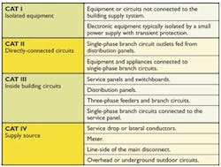
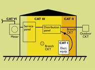
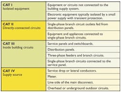
The international standard for test equipment safety is IEC 61010-1 (formerly IEC 1010-1). Table 1 shows the four measurement categories, sometimes called installation or location categories, the standard defines, as well as typical locations within a plant that fall under each category. The categories are based on the length of the conductors from the electrical service connection.Higher measurement categories apply to testing performed closer to the point of origin, where a voltage impulse delivers greater energy to connected meters. Therefore, a meter rated for a higher category features larger electrical clearances and creepage distances to withstand these impulses (see Table 2). At lower category locations, the facility wiring tends to attenuate impulses, and meter construction requirements are less demanding. When in doubt about a location, assume it falls under the higher category.Instrument ratings
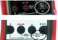
The first important rating is the measurement range. For voltage measurement, this is the maximum voltage that can be applied to the test terminals. This doesn't mean, however, that measurements can always be made safely at that voltage.Meters also should be marked with a safety category rating, which consists of a rated voltage and a measurement category, such as "600V CAT II." This marking specifies the maximum voltage that can be applied to the instrument for any type of measurement when it's connected in the category location. The latest IEC standard requires a meter to be capable of being set to any function or range with the leads connected to the maximum rated voltage without creating a hazard. Equipment can be dual-rated, for example 1000V CAT II / 600V CAT III. If a meter doesn't have a marked category rating, it's a CAT I device.Often the rated voltage is lower than the meter's measurement range. Figure 2 shows two meters with the same measurement range of 750 VAC or 1,000 VDC. The lower meter is rated for CAT III over its full range. The top one, however, is limited to 300 V in a CAT III location, and can be used on higher voltage only in a CAT II location.Select a meter with a safety rating that exceeds the anticipated application requirements for both the category and voltage. For most industrial work, 600V CAT III will be the minimum acceptable. The latest models from several manufacturers have ratings of 1,000V CAT III/600V CAT IV. Don't forget that these ratings also apply to test leads, clamp-on adapters and any other electrical accessories. The lowest rating on any of these determines the limit for the measurement.The IEC standard is voluntary, and IEC doesn't monitor compliance. Meters also should carry the listing mark of a nationally recognized testing laboratory, such as UL, ETL or CSA. Listing under UL standard 3111-1 or the newer 61010B-1 ensures that the meter complies with the IEC standard. Other UL standards, or the general terms "UL Listed" or "designed to meet," don't carry the same assurance. The European CE marking doesn't imply that a third party has verified the design. Without third-party listing, there's no way to know if the manufacturer's rating was established in accordance with IEC requirementsMeters used in explosive atmospheres are outside the scope of these standards, and must have an additional "intrinsically safe" rating. Check with the manufacturer regarding the specific application.Use the right unit
Modern meters have safety features that go a long way toward minimizing hazards. Features to look for include:
- Shrouded test lead plugs that eliminate exposed connections, even when not inserted.
- Audible alarms that sound when test lead connections don't agree with the switch setting.
- High-interrupting fuses in current-measuring circuits to prevent destructive current if the meter is improperly connected.
- More rugged case designs that minimize breakage.
- Hangers on the meter case that free both hands to make measurement without distraction.
- Test probe clips that eliminate the need to hold the probes. They make it easier to access test points safely.
- Higher safety category ratings for greater resistance to voltage impulses.
If your meters don't have these features, then it's time to replace them. Your safety depends on using proper test equipment. Choose a quality meter from one of the well-known manufacturers, and avoid bargain-priced meters that aren't as rugged, may not have verifiable safety ratings and could be dangerous in an industrial environment.People and protection
Qualified persons, according to OSHA, are those trained to avoid hazards of working on or near exposed energized electrical components. Only a qualified person should make measurements on an energized system. Anyone who performs electrical testing needs to be trained in the proper use of test equipment, as well as on each machine or system they service. For example, a worker may be qualified to test 120-volt branch circuits but not 480-volt motor controls.The minimum personal protective equipment for testing live circuits consists of insulated shoes and gloves, safety glasses and fire-retardant clothing. Also, you may need ear plugs, insulated sleeves, a face shield or a flash suit, depending on the level of shock and flash hazard that existsWatch the labels
Follow your organization's formal test procedures. In addition, observe these safety practices:
- Verify the instrument has adequate ratings for the task at hand
- Connect the test leads to the meter before making connections to the circuit.
- Whenever possible, make connections with a de-energized circuit.
- If one of the leads goes to the grounded side of the system, connect it first and disconnect it last.
- Avoid holding the instrument or leads while making the measurement.
- Never make measurements if the meter, test leads or surrounding environment are wet
Routine maintenance is critical to safety. Here are some guidelines to ensure equipment functions properly:
- Follow the manufacturer's instructions for cleaning and maintenance.
- Once a year, inspect meters for damage, replace the batteries and have them calibrated and tested.
- Never use a meter with a damaged case. Exposed internal components can present an electric shock hazard. Even a hairline crack can become conductive when exposed to moisture, grease or contaminants.
- Always replace fuses with the manufacturer's specified type and rating to ensure that they'll have the required current-interrupting capacity.
- Remove dirt and contaminants from the surface of the meter case and test probes using a damp cloth. Don't allow moisture to enter the interior of the meter.
- Avoid using harsh detergents, chemicals and solvents on the case or test leads. They can attack plastics and reduce insulation effectiveness.
Replace damaged test leads immediately. Repairs are not worth the time or safety risk.
The message
Select test equipment that has the appropriate safety ratings and features. Be sure that anyone who uses test equipment has been properly trained. Use appropriate personal protective equipment. Follow safe testing procedures. Perform regular maintenance on test equipment. You'll greatly improve your electrical testing safety when you follow these principles.
Ben Miller is an electrical consultant and safety trainer, and president of B. Miller Engineering. E-mail him at [email protected]
or call (847) 948-7746.
Figure 1: B.Miller Engineering
Figure 2: Megger Co.


