Electric utility grids rely on circuit breakers that reset automatically to isolate the faults that trees, storms, animals, lightning and auto accidents cause. This self-correction improves electric power reliability by minimizing the number of customers the fault can affect.
When a fault occurs, the affected breakers try to reset themselves within a few seconds of being tripped. They continue to do so a number of times in a coordinated manner to isolate the smallest section of the system around the fault. This technology restores power to many of the affected customers within a few seconds of the initial fault and provides an important benefit from the standpoint of power reliability.
However, these automatic reset breakers raise several power quality issues. One problem is momentary interruptions, which is a loss of voltage (power) for anywhere from 8 milliseconds (half a cycle) to a minute. Another problem is voltage sags, which are reductions in nominal voltage lasting from half a cycle to a minute. The severity of a sag is measured by the amount of voltage drop and its duration.
A costly, complex problem
Several studies researched the cost to industry of these power quality problems. One calculated the annual cost of momentary interruptions to be $52 billion. Another study focused on momentary interruptions and voltage sags to determine the cost per event and the total cost to customers. It revealed that voltage sags cost customers $7,694 per event, which translates to an annual total of $3.2 billion. The cost per momentary interruption is $11,027, and the total annual cost is $1.1 billion.
With the cost of power quality problems this high, its no wonder there are solutions that reduce it. Some of the devices that help mitigate voltage sags even claim to provide some momentary interruption ride-through capability. Most of these devices hold the motor starter contactors closed to allow the motors to remain connected to the grid. If the voltage is restored quickly, the motor comes back up to speed and continues to operate.
However, these devices have some issues. Equipment manufacturers insist that if this technology is installed on their equipment, they wont honor the warranties because, theoretically, the equipment can be damaged if the voltage is restored while the motor is still rotating.
Electromagnetic flux (emf) from the collapsing induction field, system capacitance and residual magnetism in the motor fight the field produced by the reapplied voltage. The instantaneous torque produced may exceed levels anticipated in the design of the motor or the driven machine. When asked for data to support the theoretical situation, equipment manufacturers couldnt provide any. Thats why we decided to research the matter and gather data about allowing motors to ride through momentary power interruptions.
What really happens?
Our goal was to determine what happens to a three-phase induction motor that is allowed to ride through momentary outages. The independent variables were motor rating, percent load, outage duration and load inertia. We studied 10-, 50- and 75-hp motors as they rode through momentary outages that lasted from one cycle to 100 cycles in 0.25 cycle increments. We selected four motor load operating points -- 25%, 50%, 75% and 100% -- and varied the load inertia values (Table 1) that represent three types of load.
| Inertia code | Load type | Ratio of rotor inertia to load inertia |
| 1 | Reciprocating compressor | 0.024 to 1.77 |
| 2 | Centrifugal fan | 0.59 to 7.1 |
| 3 | Centrifugal pumps | 0.024 to 0.24 |
We tested three-phase TEFC squirrel-cage induction motors and used a dynamometer as the load. A torque transducer between the motor and dynamometer measured shaft torque. A 1,024-point-per-revolution encoder attached to the torque transducer acquired shaft speed. A flywheel mounted between the dynamometer and torque transducer varied the load inertia. Our custom-built, solid-state point-on-wave controller (POWC) served two purposes. It controlled the three-phase power supplied to the motor and produced the voltage sags and momentary interruptions. A 12-channel, 1-MHz Nicolet transient analyzer recorded voltage, current, torque and speed data before, during and after the interruption.
We ran tests at each inertia and load combination shown in Table 2. After the motor reached steady-state, the POWC removed the motor supply voltage for a predetermined interruption and immediately reapplied motor supply voltage to return the motor to steady-state conditions. The interruption increment for 100% load on the 10-hp motor was 0.10 of a cycle and 0.25 cycle for the other tests.
| Motor hp rating | Inertia # (from table 1) | Horsepower load percentage | ||||
| 100% | 75% | 50% | 25% | |||
| 10-hp | A (low = real x rotor) | 1-40 cycles | 1-20 cycles | 1-20 cycles | 1-20 cycles | |
| 10-hp | B (high = 2 x rotor) | 1-40 | 1-20 | 1-20 | 1-20 | |
| 10-hp | 1 | 1-20 | 1-20 | 1-20 | 1-20 | |
| 10-hp | 2 | 1-20 | 1-20 | 1-20 | 1-20 | |
| 10-hp | 3 | 1-20 | 1-20 | 1-20 | 1-20 | |
| 50-hp | 1 | 1-20 | 1-20 | 1-20 | 1-20 | |
| 50-hp | 2 | 1-20 | 1-20 | 1-20 | 1-20 | |
| 50-hp | 3 | 1-20 | 1-20 | 1-20 | 1-20 | |
| 75-hp | 1 | 1-20 | 1-20 | 1-20 | 1-20 | |
| 75-hp | 2 | 1-20 | 1-20 | 1-20 | 1-20 | |
| 75-hp | 3 | 1-20 | 1-20 | 1-20 | 1-20 | |
Shocking results
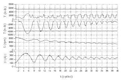
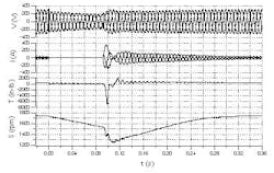
The test data revealed the effect of allowing the motor to ride through the events. The worst case for the 10-hp motor at 100% load with the load inertia ratio of 2.0 (Figure 1) occurs when power is interrupted for 92-ms (5.5 cycles on a 60-Hz line). The graphs in Table 2, from top to bottom, respectively, show the motor terminal voltage, the motor current, the shaft torque and the shaft speed, each plotted as a function of time.
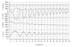
At time t=0, the motor is operating at steady-state conditions. Then, the motor supply voltage is removed and reapplied 5.5 cycles later. At that instant, the motors back-emf is approximately 194° out of phase with the incoming supply voltage. To realign rotor currents, the motor suddenly decelerates, resulting in a negative torque transient that reached 7,300 inch-pounds, 20 times the 10-hp motors rated torque. Figure 2 is a graphical representation of interruption duration. We plotted a similar graph for each load and inertia combination.
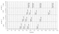
Classifying an event as safe to ride through requires minimizing the negative torque spike. Understanding the torque spike requires determining the loads effect on the motor and the loads inertia. Also, its important to determine when the most severe negative spike occurs and its magnitude. Figure 3 shows the absolute value of the most severe torque spike captured for the tests of the 10-hp motor. The motor load doesnt change the magnitude of the torque spike, only the interruption interval at which the spike occurs. On the other hand, the load inertia affects both the spikes timing and severity.
Our research shows that voltage sags are safe for ride-through because the motor field and power mains stay in synchronization. The key to an induction motors safe ride-through of many momentary outages is proper understanding of the load characteristics and proper control of the start contactor hold-in device. Our other observations should be of interest to the plant professional:
- Most severe torque spikes occur when the supply voltage is reapplied approximately 200º out of phase with the motors back-emf.
- Current transients decay fast enough to neglect heating effects.
- Varying the motor loading varies the interruption duration at which the most severe transients occur, but doesnt affect the magnitude.
- The torque, current and speed transients follow a peak/valley pattern when plotted as a function of the interruption duration.
- The shortest interruption duration at which no abnormal transients develop is a function of the inertia and the motor loading.
- More than 8,000 tests were conducted, and no significant motor damage occurred.
- The magnitude of the most severe torque transient varies with the load inertia.
The goal: Safe contact
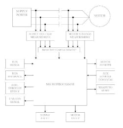
The ultimate idea was to find an industrial solution that allows motors to ride through voltage sags and momentary interruptions safely because our market research didnt find such a device. So, we developed and tested a device that achieved our goal. The device can be installed in the motor starter, where it connects to the starter and other auxiliary components. Figure 4 illustrates the schematic diagram.
The device determines when an event occurs and reacts according to the type of event. During a voltage sag, the device holds the contactors closed until the sag reaches a preset, unsafe limit, then opens the motor starter contactors and treats the event as a momentary interruption.
If the event is a momentary interruption, the device opens the motor starter contactors and monitors the motors back-emf voltage and the supply voltage. After the supply voltage has been restored, the device monitors the phase difference between the supply voltage and back-emf voltage to determine the precise moment at which the contactors must be closed to achieve a phase match. The contactors reclosure time -- the interval from the moment the contactors are told to close to the time they actually close -- is measured and tracked during every single closure. This allows the reclosure time to be factored into the split-second timing.
Tests indicate success
The device was lab tested on a Cooper Turbocompressor 250-hp 460V three-stage centrifugal air compressor. The point-on-wave switch produced the momentary interruptions, and the Nicolet transient analyzer captured the supply voltage and current, motor back-emf and device control signals. The device was integrated with the air compressors control system to control the auxiliaries needed to keep the air compressor running.
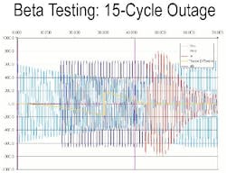
Figure 5 is a sample of the data captured during the test. The device allowed the air compressor to ride through the momentary outages the POW switch produced. The 15-cycle momentary interruption started at time zero when the contacts were told to open (pink vertical line at the extreme left side). The supply voltage returned 15 cycles later (dark blue waveform). The light blue waveform is the motors back-emf. The yellow curve is the phase difference between the supply voltage and the back-emf voltage. The first time the voltages are back in phase is at 45 cycles. The contactors were told to close at 41 cycles (second pink vertical line), and it took four cycles for them to actually close.
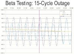
Figure 6 is an expanded-scale view of the reclosure. It shows that our device told the contactors to reclose just as the back-emf voltage and the supply voltage were coming back into phase while factoring in the time it takes for the contactors to re-close.
The final step was field testing the device. We installed it in an industrial facility in December 2004. As of June 2005, it provided safe ride-through during four momentary power interruptions and one voltage sag without exhibiting any problems. We are now planning to install our device at five more facilities before taking it to market.
Scott Peele is project manager at Progress Energy in Raleigh, N.C. Contact him at [email protected] and (709) 382-5420.
Ziba Kellum, P.E. is technical consultant at Advanced Energy in Raleigh, N.C. Contact him at [email protected] and (919) 857-9032.
Jeremy Morrison is project manager at Advanced Energy. Contact him at [email protected] and (919) 857-9037.
Rick Avery is Vice President of Business Development at Phase Solutions in Maumee, Ohio. Contact him at [email protected] and (419) 740-4401.
