Ground faults might be lurking in your variable-frequency drive systems
Driven by the benefits of resistance-grounding including concerns over arc-flash hazards, many plants that use variable frequency drives (VFDs) have installed high-resistance grounding (HRG) on the power line feeds. Some of these plants have found out the hard way that ground fault protection built into a VFD probably doesn’t work with HRG.
Variable frequency drives are used extensively in heavy industry to control rotating machinery such as compressors, pumps, conveyors, mixers and HVAC equipment. Many, if not most, of these VFDs have an integral ground-fault protection circuit. Lately, there have been reports of damaged drives because of ground faults, particularly in those operating at lower voltages (below 600 VAC).
We first became aware of this problem at a large petroleum refinery in Alberta, Canada. The refinery’s plant engineers didn’t realize the limitations of built-in ground fault protection in the drive systems. If high-resistance grounding (HRG) is installed on the power system, a VFD’s built-in ground fault protection might not work at all.
Origins of the problem
Simply put, a ground fault occurs when electricity travels through ground, instead of the intended path back to its source. More than 80% of electrical failures in equipment are ground faults caused by worn insulation, conductive dust or moisture. Deteriorated insulation on wires and cables cause 90% of these events. In cases where a person accidentally becomes a part of the ground circuit, current as low as 75 mA can send that person’s heart into ventricular fibrillation.
HRG can limit the available ground-fault current throughout a plant. It’s been used in downtime-averse process plants and explosive environments for many years, but its use is growing in other plants because of concerns about the hazards associated with arc flash. HRG limits phase-to-ground fault current and greatly reduces the risk of having an arc flash. Because HRG limits the fault current, it’s an important safety factor in limiting the energy available to a ground fault and preventing a ground fault from escalating to an arcing fault. Many plant engineers overseeing VFDs might not be aware that the drive’s ground-fault protection is incompatible with an HRG system. Many VFDs were designed for use with a solid ground instead of an HRG system. The ground-fault protection built into those VFDs should work with a solid earth ground on the feeder transformer neutral.
This isn’t the case when those VFDs are used with HRG systems. Often, a VFD’s built-in ground fault protection is set to trip at 50% of full load. However, when the VFD and its motor are connected to a system using HRG, ground fault current will never reach that 50% setpoint.
A reliable solution
There’s an easily implemented fix for this problem that can prevent the large expense associated with replacing a damaged VFD and motor. The solution is adding an appropriate ground fault relay (GFR) system, typically a microprocessor-based device that can be used with both HRG and solidly grounded systems. This type of GFR can do more than detect fault current. It can reveal leakage currents as they develop so ground faults are detected before they become critical. In fact, when properly applied, these GFRs act as preventive maintenance devices, alerting operators to a problem before equipment is damaged severely. This could save thousands of dollars in downtime, replacement parts and liability lawsuits. Relative to these costs, the price of a GFR system is negligible.
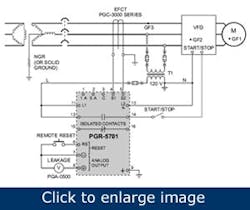
Figure 1. In this typical GFR and current transformer connection diagram, GF1, GF2 and GF3 are potential ground fault locations that must be detected by the GFR system.
To sense fault current, the GFR is used with a zero-sequence ground fault current transformer (CT). In Figure 1, T1 steps the line voltage down to match the GFR operating voltage. When a ground fault occurs on the CT’s load side, for example, at any of the points labeled GF1, GF2 or GF3, the GFR analyzes the current the CT senses; if the current suggests a ground fault, the GFR operates its output contacts and lights a trip LED. The output contacts can be connected to an alarm system, such as a PLC, or can be connected to stop the VFD or trip an upstream circuit-interrupting device. The front-panel reset button or the remote reset can unlatch the GFR trip after the fault has been corrected. Auto-reset also is selectable.
AThe trip range of certain GFRs can be adjusted from 1 to 99% of the CT primary current. Depending on the CT selected and actual fault conditions, the GFR can detect fault currents from about 50 mA to 1,000 A. In addition, the GFR trip delay time can be adjusted from 0.05 sec to 2.5 sec to provide some immunity to momentary surges and for coordination with upstream GFRs on a tripping system. Another feature is filtering the electrical noise that is created by VFDs, which prevents GFR nuisance tripping. These proprietary filters are designed to keep the GFR sensitive enough to protect both equipment and personnel.
Additional features include trip memory, test switch, self diagnostics and 0-5 V analog output. Switch-selectable algorithms are available for both fixed-frequency and variable-frequency applications. An output relay with isolated contacts can be used for independent control and alarm circuits.
Verification test circuitry
When presented with this information for the first time, plant engineers and maintenance personnel can be a bit skeptical about how well GFRs function in a VFD application. The common misperception is that a VFD isolates the load from the supply.
That was certainly the case at the Alberta refinery. The operations personnel liked what they heard but insisted on a test with one of the drive systems they use. Because they were reluctant to do this on an operational VFD in the plant, they requested witness testing of a bench-top simulation in Saskatoon.
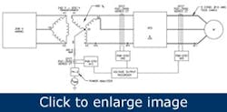
Figure 2. Basic test circuit for verifying GFR fault protection of a VFD when using HRG.
A GFR was tested for use upstream (line side) of a three-phase, 480-V, 20-hp VFD to verify the GFR’s ability to detect a ground fault downstream (load side) of the VFD (GF1 in Figure 2). Additional testing also was performed to evaluate the GFR performance with ground faults of various current levels at other locations in the system (GF2 and GF3).
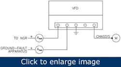
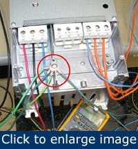
Figure 3. VFD motor chassis ground and ground current monitoring connections.
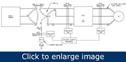
The test system included a three-phase delta-wye source with the 480-V transformer secondary neutral connected to a 200 Ω neutral-grounding resistor (NGR). The transformer’s three-phase output was connected to the VFD, which was connected through 100 ft of 3C#10 Teck cable to a 0.5-hp three-phase motor.
To configure the VFD for the testing, the various phase-to-ground capacitors, including input filters, were removed or disconnected because they’re not rated for the line-to-line voltage present during a bolted ground fault on a resistance-grounded system. The drive manufacturer’s technical support group was consulted about the best way to accomplish these modifications. This wasn’t a test system issue but is a consideration with any VFD on an HRG system.
Figure 4. Physical arrangement for VFD chassis to building ground connections.
Grounding connections for ammeters and the motor chassis were attached to a ground point on the VFD chassis. The VFD chassis was connected to the building ground, as shown in figures 3 and 4.
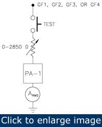
The connection shown in Figure 3 going to the ground-fault apparatus is attached to a fixed or variable resistance circuit that simulates various fault resistances (Figure 5.) One end of the circuit was connected through a push-button switch to one phase of the power circuit at various locations, and the other end was connected to ground.
This circuit simulated ground faults of various resistance levels and currents. The variable resistance could be adjusted over a range of 0-2850 Ω. As shown in Figure 5, the ground side of the simulated fault resistance circuit was connected in series with a power analyzer (PA) and an RMS ammeter.
Test procedure
Figure 5. Variable fault resistance simulator circuit.
Tests conducted in a lab to simulate the use of GFRs with a VFD system can’t simulate field-based VFD operation perfectly. The test system consisted of a single feeder with one VFD fed by a dedicated supply; the 0.5-hp motor was unloaded and the 200-Ω NGR limited fault current to 1.385 A maximum. The tests were performed at room temperature in an indoor lab and therefore didn’t simulate possible conditions that could be experienced in a field application over a long period of time. Nevertheless, test results provide a good indication of GFR capabilities under a reasonable set of conditions.
The test variables were adjustable as shown in Table 1 to simulate the power system over a range of operating conditions. The circuit variables were monitored with a power analyzer, voltage output recorder and RMS ammeters.
The power analyzer can be operated in either a wide-band mode or with a 500-Hz low-pass (LP) filter. The 500-Hz filter was necessary because the unfiltered signals contained large amounts of high-frequency noise created by the VFD, making the waveforms difficult to visualize.
| Variables | Settings |
| Output frequency of VFD | 0 Hz - 320 Hz (0.01-Hz increments) |
| Ground fault resistance | 0 Ohms - 2850 Ohms |
| GFR filter selection | Fixed or variable frequency |
| GFR trip level | 5 mA - 4.95 A (5 mA increments from 1% to 99%) |
| Fault location | Upstream or downstream of VFD, VFD DC bus and supply transformer secondary |
Table 1. Variables in VFD fault testing |
|
The transformer-to-VFD connection, VFD-to-motor connection and neutral-grounding-resistor connection were monitored using the GFR and sensitive ground-fault CTs with a 1-in. I.D. window and 5-A primary rating. The analog output (A1, A2 and A3) of each GFR is a linear 0 VDC - 5 VDC signal. When connected to a sensitive ground-fault CT, it represents the 0% - 100% rating of the CT primary current, and the analog-output scaling is 1 mV per mA of measured current. With a bolted ground fault at point GF1 in Figure 2 (i.e., fault resistance in Figure 5 set to 0 Ohms), the 200-Ω NGR limits fault current to 1.385 A. This fault current will be reduced with increased fault resistance. For example, when the fault resistance is increased to 2,850 Ω, the fault current will be 91 mA.
Test results
In the initial test, the VFD was operated at 60 Hz, and the fault circuit was set with a fairly high fault resistance. Tests were conducted with the GFR filter feature set to both fixed frequency (DFT) and variable frequency (peak detection). All three GFRs in Figure 2 tripped, with similar analog-output values, as shown in Table 2, which lists the VFD load-side ground-fault currents as measured by RMS ammeters and the power analyzer at the point of fault (fault Curr.) and at the NGR (NGR Curr.), and by the GFRs with CTs located at the NGR and upstream and downstream of the VFD (GFR Analog Output A1, A2 and A3).
| Freq (Hz) | GFR Filter | NGR Curr. (mA) | Fault Curr. (mA) | GFR Analog Output (mA) | ||||||
| Ammeter | PA-2 w/LP Filter | PA-2 w/No Filter | Ammeter | PA-1 w/LP Filter | PA-1 w/No Filter | A1 | A2 | A3 | ||
| 60 | DFT | 326 | 254 | 316 | 255 | 251 | 251 | 243 | ||
| 60 | Peak | 295 | 247 | 296 | 280 | 247 | 294 | 264 | 268 | 263 |
Table 2. Initial Test Results for Load-Side Fault (GF1) and 60 Hz VFD Operation |
||||||||||
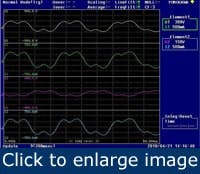
The unfiltered power analyzer values, PA-2/NoFilter and PA-1/NoFilter, are similar to the values of the RMS ammeters. The filtered power analyzer values, PA-2/LPFilter and PA-1/LPFilter, are similar to the GFR analog output values. The power analyzer captured the waveforms in Figure 6 with the 500-Hz LP filter activated. The waveforms contain many high-frequency harmonic components which are created by the drive. These high frequencies appear as noise when viewed on the PA with the 500-Hz LP filter deactivated. With the 500-Hz filter activated, a 180-Hz ripple current can be seen superimposed over the 60-Hz drive output (Figure 6). This 180-Hz ripple current was observed in subsequent tests at various VFD output frequencies.
Figure 6. PA waveforms using its 500-Hz LP filter when the test was run for a 300 mA fault and the VFD operated at 60 Hz.
This test showed that a GFR at each of the CT locations was capable of detecting a ground fault on the VFD-to-motor connection and can be used on systems with significant harmonic content. The CT and GFR should be located upstream of the VFD because this connection gives the largest protection zone. It detects a ground fault in the supply cable to the VFD, inside the VFD and downstream of the VFD.
Variable-frequency testing produced similar results. Although these details are omitted because of space limitations, the full test report can be downloaded here. The tests showed that the GFR peak-detection filter selection should be used to detect a non-60-Hz ground fault because the DFT filter is designed to ignore non-line-frequency current.
When a fault was placed on the VFD DC bus, the power analyzer showed a significant 180-Hz AC ripple component, as well as some harmonics of 180 Hz in addition to the DC component. Current transformers can’t detect DC. However, because of the sizable 180-Hz component, a CT and sensitive GFR could detect this type of fault if the GFR pickup was set to 10% of the NGR let-through current.
When placed in appropriate locations and configured properly, a high-quality GFRs can detect ground faults associated with VFDs, including when HRG is used on the power system. They can be used to add ground-fault protection to VFDs whose built-in ground-fault protection isn’t compatible with HRG. An appropriate GFR can detect a ground fault at frequencies commonly used in VFD applications, and can tolerate considerable harmonic noise.
Mervin Savostianik, P.E., is a sales engineering manager with Littelfuse, Inc., in Chicago, Illinois. Contact him at [email protected]. Ross George is an engineer at Littelfuse Startco in Saskatoon, Sask., Canada. Contact him at [email protected].
