Prepare for pressure-drop measurements
Reducing the system pressure exacerbates the effects of pressure drops across system components and can lead to problems with pressure-sensitive end-user equipment. Be prepared to locate, measure and mitigate these problems by providing for pressure-drop measurements across filters, dryers, receivers, headers and point-of-use filter/regulator/lubricator (FRL) units.
One way to measure the pressure drop across the filter is to buy a filter with a built-in differential pressure gauge. A common version shows the pressure drop across the filter using a needle that moves through a green-yellow-red field. Many such built-in devices are calibrated for 5 psid loss when clean (green) and 10 psid when dirty (red). Ask your supplier. You can always put your own markings on the faceplate.
Add measurement ports
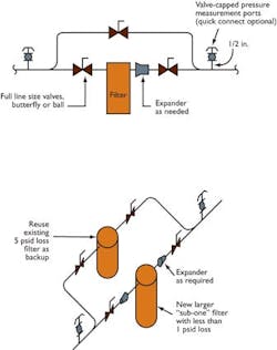
Figure 1
. Ports upstream and downstream of components allow a differential-pressure gauge to be permanently or temporarily installed to monitor conditions and diagnose pressure-drop problems.
Figure 2
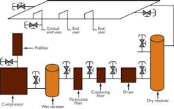
. If a new "sub-one" component with less than 1 psid loss is installed, use the old high-drop component as a backup. Another way, which offers more flexibility, is to install valved pressure ports upstream and downstream of the filter, as shown in Figures 1 and 2. In fact, it's a good idea to put these upstream and downstream of every key component in your compressed air system, not just the filters (Figure 3). The ports give you several options:- Install a permanent differential pressure gauge at each filter.
- Carry around a kit with a pair of inexpensive portable differential pressure gauges, one that reads from 0 psid to 5 psid and another that reads from 0 psid to 10 psid for your preventive maintenance checks.
- Use a high-quality (0.5% accuracy) portable differential pressure transducer and a matched hand-held digital meter to read out psid.
For an excellent diagnostic tool that gives you a window into the inner workings of your compressed air system, buy a high-quality portable setup, including a 0.5% accuracy transducer and meter pair to install at the ports upstream and downstream of key equipment, including:
- Compressor (after pre-filter) and an aftercooler.
- Particulate filter.
- Coalescing filters.
- Dryers.
- Receivers.
- Headers.
- Point of use (FRL).
Newer compressors may already have a way of checking these pressures as part of the controls. Have qualified service personnel make any changes to avoid warranty problems.
Table 1. Sub-one energy savings
*Many regulators have a pressure drop much higher than 10 psid. This is not necessarily a problem, except at the most pressure-sensitive end users.
**Many hoses have a loss much higher than 5 psid.
Regulators are an important part of the system. They step-down the high-pressure air from the header to the lower pressure the tool needs. The lower outlet pressure reduces downstream air usage and leakage. Poor regulators can block airflow partially and cause large pressure drops at end-users. Choose a high-quality regulator that opens fully, with minimum drop, for every end-user that requires pressures greater than 50 psig. If the most pressure-sensitive end user can tolerate some upward pressure excursion, consider eliminating the regulator entirely in that branch of the system. Also consider using a locking regulator, which prevents unauthorized adjustments that seem to help but really just mask the root cause of the problem.
With respect to lubricators, once again, bigger is better. A larger lubricator increases airflow and decreases pressure drop — up to a point. Follow the minimum airflow requirement if the lubricator manufacturer specifies one. Otherwise, select the lubricator for a 1 psid drop.
Also, be sure to check connections for air leaks. This further increases the savings. You may find it more economical to upgrade the entire FRL unit rather than each component separately. Common practice often results in FRL assemblies that have a combined pressure drop of 15 psid to 20 psid when clean. A little effort spent pursuing the "sub-one" criteria can net you an assembly with a clean drop of 3 psid to 5 psid.
Total savings
Upgrading hoses, filters and FRLs can cut your system energy costs as much as 15% (Table 1). For a 100 hp system, that can easily add up to saving $5,000 a year with minimal investment in new hardware. The savings from upgrading these low-cost items is only the beginning. Implementing a comprehensive optimization plan for a compressed air system achieves even greater savings.
Be prepared
Figure 3
. It's a good idea to put pressure measurement ports upstream and downstream of every key component, not just the filters.Successful upgrades
You'll want to implement upgrades without endangering critical processes. That's easy if you follow these simple steps:
- Focus on the three most pressure-sensitive areas in your plant. These are end users that won't operate if the pressure drops to unacceptably low levels. Typical examples are date coding machines, inkjet bar-coders, lathes and machine tools. Complaints from the plant floor will guide you to end users most in need of upgrade.
- Start with your worst problem area -- the one most sensitive to pressure. Make upgrades at this end user first.
- Reduce the compressor setpoint and observe the system. Check the controls to ensure the compressor with the best part-load performance is being used as the "swing" machine to handle load variations. If the pressure-sensitive end users are now operating reliably, congratulate yourself and go to step four. If not, other system deficiencies may be at play. For instance, your system may have a "gulper," a large, sudden use of compressed air that draws down system pressure and trips up those pressure-sensitive end users. Diagnosing gulpers and other problems can be tricky enough to require minute-by-minute monitoring for a few days just to determine if the problem exists.
- Move onto the next most pressure-sensitive end user and make the upgrades. Reduce the compressor setpoint again and observe the system operation.
- Continue making improvements and reducing the system pressure stepwise until the list of possible upgrades has been exhausted.
- Calculate your savings.
- Once the upgrades are complete, document your success and report the savings to management. Your hard work will pay off at your next performance review.
Compressed air success
Improving a compressed air system is neither complicated nor costly. By starting with simple upgrades to reduce system pressure, you can cut compressed air energy costs by as much as 10%. You'll also enjoy key benefits, including reduced equipment maintenance and additional compressor capacity. You'll have the pride of knowing that while your system is moving toward compliance with modern performance standards, it's also operating more efficiently and productively.
Ronald G. Wroblewski, P.E., is president of Productive Energy Solutions LLC, Madison, Wis. E-mail him at [email protected] or call (608) 232-1861.
Figures: Productive Energy Solutions LLC


