Control the flow to optimize compressor operation
During a recent audit, someone asked me a simple question - “What is the one thing I can add to every system that will ensure it always operates at optimum efficiency?” The answer is rather complex.
Let’s be clear about this. There’s no silver bullet that will ensure continuous, efficient operation in any air system, although many items of hardware have at one time or another been promoted as such. As often happens when promise doesn’t match performance, the negatives step in and imply that obviously, because the tool wasn’t perfect, it was no good. Reality lies somewhere in between. Like any piece of hardware, each has a place in some air systems. Each might be part of a good solution for achieving efficiency in an air system, depending on conditions working with some of the others. The compressed air system designer and operator must understand these products and techniques to take full advantage of the opportunities they present.
Here’s another point to be made before looking at these often-misunderstood and misapplied products: There are many things that dramatically affect the efficiency and productivity of a compressed air system, but they also might have to be adjusted before they have a positive impact. Such things as pipe sizing and configuration, air compressor selection, dryer and filter selection, automatic condensate drains selection and location, and unit capacity controls are part of success, or lack thereof.
So, what do we do about storage, pressure control, variable-speed operation, capacity control and central air management systems? How do we know what we need? How do they, or can they, work together?
Define the objective
When, exactly, is a compressed air system operating as its optimum efficiency? Some might call an efficient compressed air system an oxymoron. Evaluating a change in air supply requirements and assuming proper pipe sizing and configuration should always be verified to determine that they are acceptable.
[pullquote]An efficient system operates at optimum productivity and quality, which requires the system to be at the lowest effective discharge pressure, system header pressure and entry pressure to each process. Compressors with the best cfm/input kW ratio generally have only one unit at part load, all others at full load. There are circumstances, particularly with centrifugals, where this guideline might be modified. Air treatment equipment is at the lowest possible energy draw and pressure loss. For example, under many conditions in an oil-free system, heat-of-compression desiccant dryers can operate with no significant energy cost. Finally, the fewest possible number of air compressors are on — full load, part load or idle — as required to meet the demand. How do each of these products, with proper strategy and techniques, affect the ability to meet and hold the system at or near optimum efficiency?
Demand expander
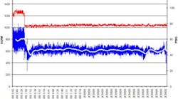
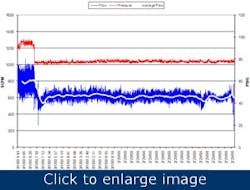
Figure 1. Controlling unregulated air will provide a stable environment in which the compressor can operate efficiently.
This also is known as a flow controller, intermediate controller, isentropic flow controller and other names. It was introduced in the late 1970s as a special air system accessory and was generally recommended with a large air receiver installed after the dryer and filter. System air then goes through the pressure regulators or computer-controlled flow control valve.
The idea is to hold the system pressure within 1 psig, thus eliminating excess header pressure, which will overdrive the demand flow by about 1% per psig of unregulated uses, including leaks. Therefore, dropping the system pressure 10 psig should reduce the leak volume by a minimum of 10%.
Table 1 shows what can be expected. When no air was regulated, the operating band was 15 psig and system “float” (maximum/minimum) was also 15 psig. Control of unregulated air absolutely does work (Figure 1). Higher pressure always drives higher flows. When the flow controller was engaged, the header pressure in this three-story manufacturing facility dropped to 80 psig from 94 psig, and the flow dropped from 800 cfm to 615 cfm.
| Compressor outlet pressure (psig) |
System entry pressure (psig) | Auto-fixed demand (cfm) | |
| Unregulated: | |||
| Cut-in |
90 | 90 | 910 |
| Run |
100 | 100 | 1000 |
| Cut out |
110 | 110 | 1054 |
| Regulated: |
|||
| Cut-in |
90 | 90 | 910 |
| Run |
100 | 90 | 910 |
| Cut out |
110 | 90 | 910 |
Table 1. This data shows the stabilizing effect the regulation provides. |
|||
Unfortunately, these systems often were oversold with statements such as:
- Don’t be concerned about any hardware upstream of the receiver because the flow controller will optimize the demand.
- The receiver will carry the peak spikes without turning on another unit.
- Every regulator requires 5 psi pressure drop, but this flow control valve only has 2 or 3 psi pressure drop.
- It will straighten out any air system; just install it.
- Run the compressors at the highest possible rated pressure; it’s most efficient at this point.
The consequences were what you would expect — sometimes it worked great, and sometimes a great deal of money was spent with no positive results. Let’s review this from an analytical angle.
If the compressor controls aren’t working properly and some units are operating at part load, it’s an expensive inefficiency and the flow controller probably won’t have any effect. The statement about the receiver is accurate, depending on a proper technical evaluation. With some supplier’s training and knowledge, this was not always done. Over time, this evolved into the belief that there’s no such thing as too big a receiver; in fact, the larger the receiver, the better. This led to some costly upgrades that, because of additional factors, still didn’t work.
Not all regulators require a specific pressure loss or drop. The pressure loss is part of the specification required to select a regulator properly. It’s not needed in all air systems and the choice might be between regulating at the point of use along with, or instead of, regulating at the headers. Will flow control benefit your system needs? What’s your system’s minimum and maximum pressure? If the float exceeds 3 psig to 4 psig, your system is a candidate for stabilized system header pressure. Also, if stable system header pressure will help productivity or quality, you are a candidate. Have you identified peaks of flow in terms of magnitude and duration? If so, a properly sized controller and receiver might well eliminate an extra unit coming online. Again, you’re a candidate.
Other comments
Compressors operating at higher pressure will cost more input energy and, in the case of reciprocating and rotary-screw or vane units, will exhibit lower overall specific power or efficiency. Storing compressed air at a higher pressure and using it at a lower pressure doesn’t give you more air. It does, however, buy time.
In many instances, a computer-controlled valve or regulator won’t make too much difference as long as the application and selection are proper. When used as a crossover valve from a high-pressure to a low-pressure system, the computer-controlled valve can read both sides and avoid completely drawing the high pressure system below a predetermined pressure.
Flow controllers are mature products, manufactured and sold by high-caliber vendors. They’re usually presented in terms of what they can accomplish. They also are easy to install as a complete package.
Pressure-flow controllers can control the pressure flow of the total system or be installed downstream closer to the point or points of use. To be installed correctly, follow these guidelines.
- Size for the maximum expected rate of flow at the lowest expected pressure. Properly done, this eliminates the chance of the valve becoming a system choke.
- Have a storage vessel of dry air ahead of the controller. The flow controller manufacturer should be able to supply the minimum size to avoid hysteresis. Oversized receivers should be considered only for control or peak use as previously described.
- Always pipe through the air receiver — in the bottom, out the top. This ensures full use of the storage whenever needed and the fastest possible response time. With a single-point connection, the receiver supplements the flow to the system during normal use. But, when system pressure rises, the receiver is taken out of the picture.
- Size the pipe to and from the flow controller to yield 20 fps to 25 fps flow and use a directional angled entry for all connections with two opposing flows. Flow from the controller to the header is at a lower pressure and might require larger pipe than the entry pipe. A second receiver after the flow controller can be advantageous under some conditions.
When the receiver is connected by a dead-end line, pressure rises faster in the pipe than in the receiver. When the demand exceeds the primary compressed air supply, the trim unit comes online. In this example, the 10 psig operating band of 95 psig to 105 psig occurs in the single pipe for 10 seconds. During this same interval, the receiver pressure rises from 95 psig to 97 psig. Within several seconds, air from the receiver is blocked from entering the system. This results in the trim unit short cycling (load 10 seconds/no load 10 seconds) providing about only 50% of the trim unit capacity into the system during each 60-second interval.
However, when the air passes through the receiver, piping and receiver pressure now rise and fall together. The pump-up cycle is now almost 2 minutes and 100% of the full-load capacity is put into the system in 60 seconds. The compressor runs loaded for the same time to put the same amount of air into the system, but takes twice as long (2 min loaded at 100% power). Short cycling is also very hard on the equipment.
Air receiver storage
“The Compressed Air Receiver: the Endless Question,” published in Plant Services in 1997, gives detailed explanation of air receiver storage. However, let’s review this in the context of compressed air system efficiency and control.
Receivers ahead of dust collectors ensure that high rates don’t drop the inlet pressure so low the pulse becomes ineffective and doesn’t clear the bag. Every dust collector should have proper storage sized to the specific application installed at or near its entry point.
Hank van Ormer owns Air Power USA Inc. Contact him at [email protected] and (740) 862-4112.

