Variable-speed drives and central control systems help compressors achieve efficiency and reliability
In the industrial compressor market, most variable-speed drives (VSDs) are found on rotary-screw and rotary-vane compressors; however, VSDs can do well on reciprocating units and VSD centrifugal compressors running on magnetic bearings, which can be an excellent trim compressor under the proper conditions.
[pullquote]These units have been available on the aftermarket for decades. Like so many other products, when VSDs were introduced as factory packages on rotary compressors, most manufacturers saw them as an instant fix for numerous air system inefficiencies. Many plants bought this configuration, even if no real need existed and even if there were other options offering more efficiency for less capital cost. Some thought that if one was good, two were better. VSD units purchased as trim units installed with a central control system couldn’t always maintain proper alignment.
The VSD is the most power-efficient unloading control for lubricant-cooled rotary screw compressors operating from 75% to 80% load down to the lowest at which it can operate. The most power-effective approach from 75% to 100% load is the variable-displacement concept, which usually unloads the compressor in four steps of 12.5%, down to 50% and then defaults to base control below that.
With two-stage, oil-free, rotary screw compressors, the VSD often isn’t significantly more efficient than the standard constant-speed two-step control. However, it’s easy to install and avoids short cycling.
As is the case with every important decision, pay attention to detail when selecting a VSD. Know the demand profile. Know how each VSD unit on your compressors will match up with your profile. A VSD of any design will use from additional power draw compared to operating at constant speed.
Consider rotary-screw compressors operating 8,000 hours/year and producing 490 acfm at 100 psig using 110 bhp on a 460 V/60 Hz/3 Ph circuit, where power costs $0.06/kWh.
Constant-speed drive:
133 A
Power factor = 0.91
Mechanical efficiency = 0.923 x pf = 0.84
Efficiency = 3.684 cfm/A
Power draw = (133 x 460 x 1.732 x 0.84)/1,000 = 89.0 kW
Annual cost = 89 kW x $0.06/kWh x 8,000 hr = $42,720/yr
Variable-speed drive:
130 A
Power factor = 0.98
Mechanical efficiency = 0.958 x pf = 0.944
Efficiency = 3.769 cfm/A
Power draw = (130 x 460 x 1.732 x 0.944)/1,000 = 97.8 kW
Annual cost = 97.8 kW x $0.06/kWh x 8,000 hr = $46,931/yr
Variable-speed drive is 9% less efficient than a constant-speed drive at full load for the same flow and pressure: (46,931-42,720)/46,931 = 0.0897.
Compressor manufacturers use several types of VSD units. These include:
- Variable frequency drive (VFD)
- Switched reluctance drive (SRD)
- Permanent magnet.
VSD compressors don’t exhibit the same performance. Know what you’re reviewing. Get a complete performance curve of scfm/input kW throughout the operating band. This is standard manufacturer operating data. Most systems need only one VSD trim unit. Some situations might be able to use multiple drives more successfully, but be sure to review the operating data in detail. Many factory VSD packages limit the top speed to fit the discharge pressure you select. The higher the pressure setting, the slower will be the full-load speed and the delivered air flow. If you find you can run at a lower pressure, often the electronic controller can be reset to a lower pressure, faster speed and more air.
How does the VSD fit into this system control scenario? The VSD can hold a discharge pressure within 1 psig to 2 psig, so you usually don’t need a flow controller and VSD for trim to hold a steady discharge pressure on the same system. Even with a VSD control, we generally recommend storage to smooth out the flows and give enough time for proper switching.
Central control systems
There are few systems with three or more units that can’t benefit from an effective central air management system. Modern systems sense, or calculate, the coming change before it occurs and quickly take appropriate action, sometimes even before evidence appears in the system.
To make it work, you’ve got to know what you’re doing now that creates poor efficiency, what you want the central air management to accomplish, the recoverable energy cost and how much you must invest to achieve the proper return on investment. Many suppliers of central control systems also are compressor manufacturers, independent, HVAC control companies and the like. Each offers an “intelligent” microprocessor that minimizes energy cost and maximum energy savings.
Early systems often were called alternators or sequencers. The basic protocol was pressure-based as typified by the cascade-type control system (Figure 1).
Figure 1. In cascade control, four compressors, each with a 10-psig operating band, are programmed slightly differently to achieve smooth operation of the overall system. As system pressure deviates from the desired 85-psig minimum to 110-psig maximum, on-board capacity controls load and unload the units.
Modern communication equipment eliminated this pressure-based system in favor of a single target set point pressure that is read from a stable source. Now, we can run the same four units, but over only a 10-psig operating band (85 psig to 95 psig) most of the time. Because this system is pressure-based, nothing happens until system pressure changes.
There are many different protocols with this type of system, some are more reactive than others, but also more expensive. You don’t need to purchase more than you need. Some differences include:
- PID controller to include rate-of-change in the calculations
- Use fuzzy logic as required to shorten reaction time
- Either responds only with a preset sequence alignment or is capable of analyzing available air and selecting the proper unit by size and/or performance
The most prevalent question for these types of central control systems is: “Can you run all units at full-load, except one at part load 85% to 95% of the time?” Many of these systems have problems when a VSD unit isn’t considered in the calculated protocol. The high-performance central air management systems are flow-based, meaning they use a continuing stream of flow data to analyze what’s going on. These protocols are proactive, often picking up data before the change occurs. The flow values to drive the system are usually obtained by several sources:
- Measured flow determined by calibrated and properly-installed flow meters
- Calculated flow from OEM test data (or field test data) using input kW and proper motor and capacity control data
- Other specific measured operating data points, such as pressure below the inlet valve compared to ambient, pressure to the inlet valve positioner, location of inlet valve positioner, locations of blow off air
- With mass flow units, particularly, detailed air-inlet conditions are measured to allow full calculation to reflect the inlet ambient condition’s effect on compressor performance
Older types of software still use a pressure-actuated cascade protocol with closer tolerance. Newer software:
- Keeps all except one unit at full-load
- Measures percentage part load
- Forces a unit to full-load when possible
- Reacts to rate-of-change, but also measures and reads inlet conditions
- Identifies and verifies compressor’s load points (kW input, inlet vacuum, other)
- Adjusts compressor choice as required for the most power efficient grouping
- Targets the set points
- Doesn’t require or use a preset sequence
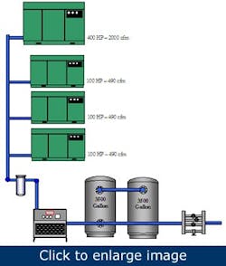
This large central air management system didn’t work. The 400-hp unit was converted from variable-displacement control to two-step (load/no load) control and pressure fell to the cut-in point. A 100-hp unit came online and added 490 acfm. The pressure in the discharge line then rises to the 400-hp unload point (storage tank, single point connection). The 400-hp unit unloads and removes 1,900 acfm from system and the pressure falls quickly. Two more 100-hp units turn on (adding 980 acfm) and the 400-hp partially loaded unit starts. One or two units then short-cycle most of the rest of the day.
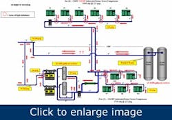
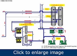
This design also didn’t work. It had two 30,000-gal tanks about 500 ft from the compressor room. All the air went into and out of the receiver along the same line. When pressure fell, the trim unit raised the line pressure very little and no air left the two receivers. The air in the receivers might have been 25 years old. The corrected system moved the receivers closer, separated the line to the receivers (tied together) and separated the lines from them. The piping and storage now act in concert.
Hank van Ormer owns Air Power USA in Pickerington, Ohio. Contact him at [email protected] and (740) 862-4112.


