Top tips for choosing a centrifugal compressor
In brief:
- Compressor selection should be based on an evaluation of technical and commercial factors and this should be completed before placing an order. Integrally-geared compressors are relatively new to process applications and involve more complex dynamic behavior, more vibration and dynamic factors, and usually narrower operating margins. But, the integrally geared configuration can be one of most efficient and compact designs for centrifugal compressors.
- One of the main applications for integrally geared machines is small- and medium-size constant-speed motor-driven centrifugal compressors where a variable speed drive isn’t feasible. Integrally geared machines driven by synchronous motors require special considerations. Integrally geared centrifugal compressors are usually around 15% to 30% less expensive, around a 10% to 15% shorter fabrication period. In spite of lower prices, they introduce more risks, less reliability and more maintenance
- Integrally-geared machines can reach an equivalent pressure using fewer impellers and higher maximum tip speeds. Both efficiency and pressure coefficient are higher for semi-open overhung three-dimensional impellers, usually found in integrally geared machines. One disadvantage of an integrally geared compressor is that each impeller needs to be sealed, an arrangement for which labyrinth seals are acceptable.
Centrifugal compressors are dynamic machines in which rotating impellers accelerate the gas. Main flow is radial. The velocity head is converted into pressure, partially in the rotating elements and partially in stationary diffusers. There are many configurations of centrifugal compressor that can do this. The integrally geared configuration is an overhung style machine installed on a gear system that uses the gear pinion shaft extensions to mount impellers. The individual compressor casing is attached to the gear system main casing.
The most common form is a packaged plant air compressor (covered by American Petroleum Institute (API) 672) but in the most recent two decades, integrally geared centrifugal compressors were introduced for process applications and recognized by API 617. Evaluation and purchasing of centrifugal compressors is an involved optimization process with respect to the full array of compressor data. Otherwise, you might end up with equipment that isn’t suitable for the full operating range, reliability, maintainability, availability, commercial terms or power requirement you expect.
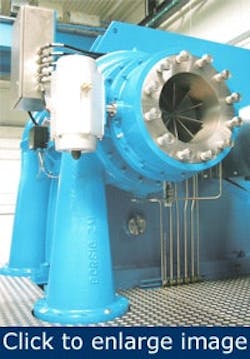
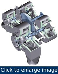
Figure 1. The pinions in an integrally geared multi-stage centrifugal compressor don’t need to rotate at the same speed.
A concern in the bidding stage is the correct choice between classic, reliable, low risk conventional type (driver, gear unit and multi-casing machine) and new, compact and relatively cheaper integrally geared machines. Some people evaluate reliability and risk issues first, with the initial cost and other factors as secondary. This reliability-versus-other-factors trade-off usually helps to bring more centrifugal compressors into various process applications. However, this approach might lead to selecting conventional-type centrifugal compressors for every application without considering advantages of integrally geared machines for specific applications.
Compressor selection should be based on a thorough evaluation of technical and commercial factors to ensure the best machine is purchased. But you’ll need to know the different design and operation aspects of both the conventional type and the integrally geared type.
General process considerations
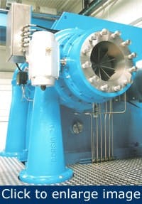
Figure 2. This is an example of an integrally geared centrifugal compressor for process applications.
Although conventional designs having proven in-service history and reliability are preferred, this shouldn’t preclude the introduction of new integrally geared compressors. This is particularly relevant if advantages in cost, effectiveness, operational efficiency and reduced footprint can be gained. Total cost of ownership (TCO) is one of the main considerations in evaluation and selection.
In general, select the machine with the lowest expected TCO. Integrally geared centrifugal compressors are capable of a wide range of capacity and pressure, but they’re not commonly used for pressures greater than 4,300 psi.
Advantages of integrally geared compressor
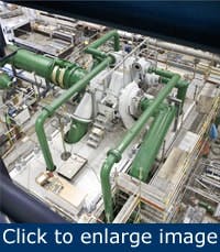
They’re relatively new for process applications, in spite of a long history in auxiliaries such as air compression. The integrally geared configuration uses a main big gear to rotate several pinions, each coupled to one or two overhung centrifugal impellers. The pinion shafts can operate at different speeds, allowing each stage in a multi-stage machine to be run at its own optimum speed. Figure 1 and Figure 2 show integrally geared centrifugal compressors. Multi-stage integrally geared units handle many process gases in CPI plants (Figure 3).
It’s economically desirable to use the smallest possible machine. The head an impeller can develop depends on its pressure coefficient. Both efficiency and pressure coefficient are higher for semi-open overhung three-dimensional impellers, usually found in integrally geared machines. Semi-open impellers, have considerably higher pressure ratio capability, about two times to three times more than closed impellers.
Figure 3. This packaged integrally geared centrifugal compressor is an example of what might be found in a petrochemical plant.
This means integrally geared machines can reach an equivalent pressure using fewer impellers. Maximum tip speed of semi-open impellers, usually integrally geared, is about 30% more than a closed impeller. Variable guide vanes are the preferred method of capacity control to meet varying operating conditions (efficient part load operation). One of the main applications for integrally geared machines is small- and medium-size constant-speed motor-driven centrifugal compressors where a variable speed drive isn’t feasible.
Integrally geared machines aren’t recommended with variable speed drives, synchronous motors and gas or steam turbine drives. In spite of this, some successful references are available, but detailed studies don’t support these applications and dynamic responses are unnecessarily complex.
The pinion shafts on integrally geared compressors usually have no thrust bearing. The thrust is partly balanced, in the case of two impellers mounted on one pinion, and also balanced against the helical gear or transmitted to the bull gear thrust bearing by means of thrust rider rings fixed to the pinions and bull gear. Axial location is controlled by a thrust face on the pinion facing the bull gear. The latter has a double acting thrust bearing. Thrust loads from impellers and gears are sometimes absorbed by individual thrust bearings on pinions; it’s a special design. Balance pistons normally aren’t used in integrally geared machines.
Integrally geared centrifugal compressors are better in terms of commercial factors — usually around 15% to 30% less expensive, around a 10% to 15% shorter fabrication period. This combined with slightly higher efficiency and compact design lead to considerable initial and operation cost reductions. Compressor manufacturers try to sell integrally geared process centrifugal compressors because they need a history of more successes in CPI plants.
Other factors include less outsourcing required, eliminating gear unit sub-suppliers; a need for only one coupling; and inherently simpler and cheaper machines. For some applications, such as in revamp projects where available space and commercial factors are major limitations, integrally geared machines can be the best solution. In some cases, better commercial conditions or compact design make a project feasible. There were some revamp projects implemented using integrally geared machines, which weren’t feasible with conventional compressors.
Disadvantages of integrally geared compressors
One disadvantage of an integrally geared compressor is that each impeller needs to be sealed, an arrangement for which labyrinth seals are acceptable. This is one reason integrally geared units were being used for air supply systems long before process applications. API 672 was developed for packaged integrally geared units for air many years before API 617 appreciated them for process applications. Integrally geared compressors involve more complex dynamic behavior, introduce more vibration and dynamic factors, and usually have narrower operating margins.
Vendors usually provide a long list of deviations from API 617 when you purchase an integrally geared machine. Generally, they’re built with more OEM standard components and more deviations from various codes and APIs standards. Compared to conventional machines, integrally geared models have less history in process plants and they’re not popular with major process companies.
In spite of lower prices, they introduce more risks, less reliability and more maintenance. There’s a potential risk that the unit could be an untested prototype. Using integrally geared centrifugal compressors with steam turbines, variable speed motors or drivers that introduce transient load variations isn’t a suitable option. An integrally geared machine is more sensitive to unbalance than the conventional type. If you anticipate impeller fouling, an integrally geared design might not be suitable. Integrally geared machine are usually used for molecular weights less than 46.
Conventional compressor
The common conventional arrangement is a tandem-driven series flow configuration using a common driver. A gear unit generally is included in the compressor train. The maximum number of compressors using one driver is generally limited to four. Installations with seven or eight separately driven and connected in a series have been reported.
Compact integrally geared machines can help avoid long conventional trains. However, this selection depends on the application. You’ll need careful case-by-case studies and assessments. An example is a 25-MW centrifugal compressor train for a methanol plant.
[pullquote]The unit is driven by steam turbine. It’s an application for which an integrally geared machine isn’t feasible. The four barrels are arranged in an H configuration on the two sides of the multiple shaft gear box. This example of a conventional multi-casing arrangement avoids a long train. A great advantage of the conventional type train is the accumulated knowledge and experience in design and fabrication of API 613 special-purpose gear systems.
They’re proven in-service and are reliable gear units with many references in process plants and lots of accumulated knowledge and experience. The specifications and vendor knowledge and experience with integrally geared machines haven’t reached the sophistication of API 613 special-purpose gear units. Many references for both systems might be the same on paper, but there are still considerable gaps in various fields.
Special considerations
The confusion comes with the use of the word “stage” for various types of centrifugal compressor. To the compressor manufacturers and mechanical engineers, a stage is an impeller or impeller-diffuser pair in conventional type. Process engineers tend to think of a stage as a process block that equates to an uncooled section, which usually includes several open impellers in an integrally geared machine or several impeller-diffuser pairs in a conventional type. It’s a main source of confusion when dealing with centrifugal compressors. To solve the issue, a process compression stage is referred to as an uncooled section or process stage.
Special care is needed when an integrally geared machine has any gear set with a ratio of 7:1 or greater. These gear sets are rated in accordance with Annex 3F of API 617, which is based on American Gear Manufacturers Association (AGMA) 2101 with a safety factor 1.25 to provide increased reliability. If the pitch line velocity exceeds 24,000 ft/min, give consideration to design features such as windage baffles, false bottoms, adequate sump depth and additional full-size drains.
Integrally geared machines driven by synchronous motors also require special considerations. Minimum gear service factor for integrally geared machine is 1.4 for induction motor driven, 1.6 for gas or steam turbine driven, and 1.7 for synchronous motor or internal combustion engine driven. Consider the following for gear set design in integrally geared machine.
- Preferred design is to wear out before breaking. Failure occurs from pitting rather than bending.
- Minimum gear material requirement is AGMA 2101 Grade 2 material.
- Pinion should have the teeth integral with shaft.
- No break-in period is required.
- Hunting tooth combinations are strongly preferred. Every tooth on the gear engages every tooth on the pinion at some point in time to prevent wear patterns developing. If necessary, vendor should adjust the exact gear ratio.
- Each gear and pinion should be supported between bearings.
Use casing vibration sensors mounted on the main casing near the pinion bearings to better measure gear-mesh vibration. For specific applications, you should copy similar integrally geared machines that have been in service for more than three years and have at least a single unit with more than 25,000 operational running hours. Forces and moments allowed on integrally geared compressors are generally less than the values permitted on conventional type compressors. Applicable codes don’t specify these loads because limiting criteria are the gear contact pattern and the impeller/stator gap, which depend on various complex variables such as volute design or compressor and gear system design.
These are important for this type of machine and should be settled before placing an order. There are many cases of expansion joints installed on integrally geared compressor piping to minimize the loads. This means more cost and less reliability.
A removable, gasketed inspection cover is required in the gear casing to permit direct visual inspection of the full-face width of the pinions and gear. Permanent coating or paint isn’t recommended for the casing interior. If you use a variable inlet guide vane system for integrally geared machines, consider these suggestions.
- Locate it as close as possible to the impeller eye.
- Interactions of process and actuator/linkage systems used for toxic, flammable or explosive process gas require careful studies. A proper seal is required for linkage passing through the casing or enclosure to prevent leakage.
- A cantilevered design in lieu of a center-supported vane design is preferred.
- Vanes designed “fail to open” (open on loss of the control signal).
Integrally geared machines have only one low-speed coupling, situated between the driver and bull gear. Best practices suggest using high torsional stiffness couplings; however, a coupling containing elastonomers is sometimes needed. Integrally geared compressors are fixed to the mounting plate and shouldn’t normally be moved for alignment to avoid gear system distortion.
Case studies
The first case study concerns a 13-MW steam turbine-driven unit that compresses carbon dioxide from atmospheric pressure to about 2,200 psi for a urea plant. The integrally geared machine had eight stages — four pinions connected to the bull gear. The proposed conventional in-line compressor was a four-stage machine, each stage featuring three or four closed impellers. To achieve the same compression ratio as an eight-stage integrally geared unit, the compression had to be split into two casings, each carrying two stages with a step-up gear between them. Integrally geared references using an electric motor were available, but the vendor didn’t have comparable references using steam turbines.
Detailed dynamic studies showed that the integrally geared machine is unnecessarily complex and tends to encounter some problems and limitations in a specified variable speed range. The conventional compressor had more than five references in similar applications — steam turbine drive, capacity, pressure range. Taking into consideration the vendor’s extensive experience and fewer deviations from API standards, we selected the conventional machine.
The second case study is a 1-MW constant-speed motor-driven natural gas compressor for a process plant. A main consideration was capacity control. For conventional centrifugal compressors, the best, more efficient method of control is by changing the speed. But variable speed using a variable speed drive wasn’t feasible because of the relatively high cost. Taking into account better commercial terms such as lower cost and shorter fabrication period, better efficiency, smaller limited footprint and capacity control, we selected the integrally geared centrifugal compressor.
Integrally geared configuration is one of most efficient and compact available designs for centrifugal compressors. It has been identified as potential growth market. Situations that make the integrally geared centrifugal compressor a main option include:
- Small- and medium-size centrifugal compressor that uses constant-speed electric motor as driver (conventional type compressor is still preferred option for variable speed driver such as steam turbine, gas turbine, electric motor with variable speed drive)
- Revamp or low-budget project for which the available footprint or resources only match using an integrally geared machine
- Inert gases such as air or nitrogen.
An integrally geared compressor, if suitable references are available, should not be precluded before making a detailed assessment and evaluation. Careful study and a technical/commercial evaluation are absolutely necessary for machine arrangement and choosing between an integrally geared unit, a conventional train or modern alternative such as conventional compressor train with H-type configuration.
Amin Almasi is lead rotating equipment engineer at WorleyParsons Services in Brisbane, Australia. Contact him at [email protected] and 61 (0)7-3319-3902.


