Central or departmental compressed air system?
In brief:
- Early on, PVC was used for compressed air piping, and it wasn’t long before it became evident that PVC sometimes shattered when it failed, sending sharp pieces throughout the area.
- Copper pipe is a common selection for sensitive air systems. It’s very rugged when selected and connected correctly.
- Air condensate tends to be acidic. In oil-free compressors, it’s usually particularly aggressive without the oil to neutralize it.
Which is better — a classical centralized air system or a departmental compressed air system? Reports suggest that neither system is better. Quite often, the right choice is a combination or variation of both. Here’s why.
A central air system satisfies total air demand for total plant operations. Air provided by one or more compressors is distributed from a central supply point to areas requiring air service. Compressors in such a system are commonly installed in a powerhouse area with other utilities.
In a departmental air system, several air compressors are located at principal points of use throughout the plant. This approach can be used instead of, or in combination with, the central type.
Variation can pay
Each has its advantages and disadvantages. In deciding which is best for your needs, weigh the total benefits gained against the drawbacks that go with the choice. The case for one system over the other isn’t always clear cut. The judicious plant engineer, after weighing the facts and figures, might arrive at a combination of both, or even a variation. Here’s a hypothetical example.
A 50,000-cfm centralized air system has several centrifugal compressors. They’re the most efficient and economical for this size application. However, the units have a 100-psig maximum discharge pressure. The plant requires 2,100 cfm at 150 psig in one department, 24 hours a day. Two options are available.
- Install a complete air system delivering 2,100 cfm at 150 psig in the department. A complete system such as this will use about 500 hp and cost approximately $150,000 to $175,000 uninstalled.
- Install a booster compressor to provide the required 2,100 cfm by kicking the 100-psig system pressure to the required 150 psig. A correctly applied, double-acting, single-stage reciprocating booster, requiring only 125 hp, will do the job for about $40,000 to $50,000, uninstalled.
Obviously, this small booster represents tremendous savings. At a utility cost of $0.04/kWh, a savings up to 375 hp can amount to more than $100,000 per year in power savings alone, not including the cost of the 100 psig inlet air. If all or part of the 2,100 cfm of 100-psig air is available from blow off, this might generate significant savings. While this is but one example, there are many situations offering the plant engineer a chance to save on air system installation and operating costs. It takes careful planning and correctly applied knowledge of compressed air, compressed air systems and compressed air equipment.
It’s important to understand the classical approaches to compressed air systems and air compressor selection. You also should be aware of what modern materials, air compressor design and compressed air requirements have done to increase the opportunities for both initial and continuing cost saving.
[pullquote]To get more work and efficiency out of compressors, many manufacturers of air production machinery and tools now require higher pressure and higher quality air that’s dryer and cleaner than the standard aftercooler untreated air. Air compressor manufacturers responded with a variety of machine designs that allow the system engineer many options.
High-performance, oil-cooled rotary compressors, both vane and screw types available as fully packaged air systems offer nearly complete installation flexibility. These continuous duty units with air-cooled and water-cooled oil coolers are relatively small and very quiet. They can be used for departmental air and compromise nothing in durability. Single-stage, oil-cooled rotaries offer full load pressures to 175 psig, and two-stage units can go even higher.
Rotary units, lobe or screw type, non-lube, air or water-cooled, two-stage compressors provide good efficiency and continuous duty from 50 hp to 600 hp. They’re usually higher in initial cost and somewhat less efficient than the air-cooled two-stage lubricant-cooled rotaries. Single and two-stage double-acting reciprocating, water-cooled units are the most expensive to buy and install, but they’re also often the most efficient. Therefore, they have the lowest power cost compared with other types of similar sizes.
Modern air compressor design produced heavy-duty, short-stroke, higher-rpm, smooth-running, lightweight, single-acting reciprocating, air- and water-cooled units that require no special foundation. They’re quite suitable for providing high pressure air for localized or departmental applications. Heavy-duty units generally are available from 5 hp to 75 hp, 20 cfm to 170 cfm and 150 psig to 5,000 psig. They often serve as departmental air to supply a special process requirement.
The need for air filters that deliver instrument-quality, oil-free air continues to increase. Filter technology has come so far in recent years that virtually any degree of cleanliness can be reached economically with reasonabe or no pressure drop.
After you determine what kind of system best suits your plant, you must address other considerations.
- What kind of air distribution system?
- What will be the key air supplier?
- Is the air lubricated or non-lubricated?
- Should the compressed air be dried?
- If so, then how dry, how clean and how much hydrocarbon is acceptable?
Centralized system: advantages and disadvantages
Centralized systems have several advantages.
- Maintenance and care are simplified because the units are in one area. In the event an overhaul is needed, the lifting/transport equipment and tools usually are available nearby.
- Important utilities, such as water and electric, are located in the same area.
- It’s more efficient to centralize the storage and drying of air compared with dispersing those functions.
- Larger air compressors generally are used in a centralized system. These offer longer maintenance intervals than smaller air-cooled units and probably better specific power.
- Heat reclamation from the air and oil coolers of industrial duty rotary screw compressors can help to reduce plant heating costs. This form of energy conservation is achieved more effectively from a central system.
There are disadvantages to a central system, too.
- A centralized system requires larger and more expensive air pipes to avoid energy-draining pressure losses associated with carrying greater volumes of air longer distances.
- Central air doesn’t satisfy localized demand for different, particularly higher, air pressures.
- The air quality isn’t easily varied. Some applications might require non-lubricated air or very dry air, while others won’t. We generally recommend drying the air to at least a +40°F pressure dewpoint.
Departmental system: advantages and disadvantages
A departmentalized system offers certain advantages.
- Smaller and less expensive air lines carry smaller amounts of air shorter distances. Thus, effective air systems can be installed at lower cost and with minimum pressure losses. Smaller compressors might well have lower specified power ratings.
- Varying air pressures can be provided easily to meet each department’s requirements.
- Any quality can be delivered to each department as required without over-cleaning or over-drying the total system.
- Correct piping procedures allow tying the various departmental air systems together, enabling each department’s air system to back up the other.
The disadvantages of a departmental system are numerous, as well.
- When compressors are spread out, maintenance and service tend to be more of a problem. Sometimes there’s uncertainty about who is responsible and less diligence about getting the job done. Service might need to be relegated to the using department, rather than centralized plant maintenance.
- The plant might have to bring in specialized equipment for major overhauls.
- Adequate water and electric power might be hard to bring in for units that require them. However, this disadvantage can be mitigated by using smaller air-cooled compressors if they’re adequate for departmental air needs.
- Installation is more complex for a central air management system.
Pipe for central systems
Compressed air piping probably has had more pages written about it than any other topic, even storage. Like many other topics in practical compressed air technology, a significant portion is controversial. These guidelines aren’t intended to replace the appropriate correct volumes of information or misinformation and aren’t designed to answer all questions regarding a specific installation. They’re designed to provide basic principles that always apply and, when followed, provide a well-performing system. As with any set of guidelines, they’re based on performance and measured critical field data molded with theoretical performance.
Types of piping
Consult federal, state and local codes before deciding on the type of piping to be used. The usual standard to be applied is ASME B31.1. For health care facilities, consult the current Standard NFPA 99 of the National Fire Protection Association. The compressed air piping materials can be divided into two types: metal and non-metal.
Non-metal pipe, commonly called “plastic” pipe, has been offered for many years as compressed air piping.
- It’s lighter than most metal and easier to handle.
- It can be installed without special tools such as welders or pipe dies.
- It’s generally non-corrosive.
- Installation with the appropriate gluing material is fast.
- The labor cost, which can be unskilled, is much lower than for most metals (copper, stainless, black iron), and the system often can be installed less expensively.
Early on, PVC was used for compressed air piping, and it wasn’t long before it became evident that PVC sometimes shattered when it failed, sending sharp pieces throughout the area. New pipe products used material that didn’t shatter. However, this material and others offered to date have significant limitations.
- Most are limited to an operating temperature of 140 °F to 200 °F. A non-performing aftercooler can easily reach or exceed these numbers. PVC, for instance, is limited to about 160 °F at 125 psig, but it starts to weaken at 70 °F.
- Most of these materials aren’t compatible with compressor oils in general, and many synthetics in particular.
- Although pipeline fires are rare, when there’s one in plastic pipe, there’s a good chance that it will melt the plastic pipe and migrate around the plant.
- A fire in the plant with the compressed air line active could melt the pipe from the outside causing additional catastrophic problems.
- If new thermoplastic materials are used, the piping system becomes quite expensive, certainly more than a high-quality extruded aluminum alloy with push-to-connect or compression fitting connections.
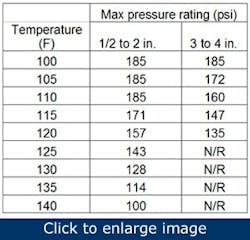
As with other thermoplastic components, the maximum non-shock operating pressure is a function of temperature (Table 1). The heat of compression should be removed fully so as not to exceed the maximum temperature rating (140 °F for 1/2-in. PVC, 120 °F for 3/4-in. PVC).
Table 1. Typical pressure limits for thermoplastic pipe and fittings are a function of temperature and line size. (N/R = not recommended)
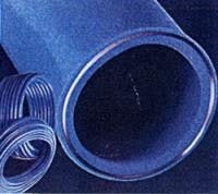
Figure 1. Even HDPE plastic pipe with an aluminum core is still rated at 73 °F and 140 °F. It doesn’t have published testing above 140 °F. Resistance to common oils and solvents isn’t published.
The pressure ratings for typical thermoplastic piping and fittings are a nearly constant 185 psi for all line sizes at temperatures from -20 °F to 100 °F, and are gradually reduced above 100 °F. The compressed air industry hasn’t accepted any type of plastic pipe as appropriate and safe for discharge and downstream compressed air (Figure 1, Figure 2). I agree with this view, given today’s material, data and available alternatives. There are no apparent benefits to offset the risk.
Metallic options
Metal pipe can be black iron, stainless steel, copper or extruded aluminum alloy, having appropriate thermal and pressure characteristics.
Black iron or steel pipe in compressed air systems corrodes when exposed to condensate and thus becomes a source of system contamination. This pipe is usually a threaded 3-in. or smaller and is welded or flanged to pipe of a larger diameter.
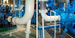
Figure 2. Nonmetallic pipe is installed on two air compressors with built in air-cooled aftercoolers and air-cooled refrigerant dryers. Compressor discharge can be a normal 200 oF with synthetic oil carryover. Failure of either the aftercooler or dryer, plus fouling of the auto drain could endanger system integrity. Note the dead head connection.
Compared to copper and extruded aluminum alloy, it’s much heavier and harder to install, but less expensive. Internal corrosion is much more significant with oil-free air and associated aggressive high-acid condensate characteristic than with lubricated compressors.
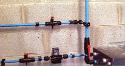
Extruded aluminum-alloy and stainless-steel compressed air piping has become popular. They provide a smooth, low-friction inner surface and eliminate self-contamination but also offer enhanced flexibility to meet ever-changing air distribution needs. This is particularly desirable in such plants as the automotive support industry with evolving assembly and subassembly areas. Most extruded aluminum alloy pipe is rated at +4 °F to 140 °F or 176 °F. The piping material usually has a melting point greater than 1,100 °F. For maximum flexibility, these often are installed with reusable fittings (Figure 3).
Figure 3. Extruded aluminum alloy air system piping can have connections that require no special tools or pipe threading.
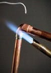
Figure 4. Never join air line fittings by soldering with lead-tin solders, which have a low ultimate strength, a low creep limit and, depending on the alloy, start melting at 361°F. Silver soldering and hard soldering with silver-alloy filler material are forms of brazing and should not be confused with lead-tin soldering. The alloy melts in the range of 1,145°F to 1,800°F.
Copper pipe is a common selection for sensitive air systems. It’s very rugged when selected and connected correctly. Its working pressure is 250 psi for Type M hard, Type L hard and Type K soft, and 400 psi for Type K hard. Because 50/50 solder melts at 421 °F, copper lines are more resistant to high temperatures (Figure 4). If it does fail, it will do so in a predictable manner — the pipe ends will separate. According to the Piping Handbook, 6th edition, the working temperature limit for copper piping is about 400 °F.
Extruded aluminum alloy pipe can be installed in most areas where copper can be used aluminum. Alloy offers some significant advantages:
- much lower initial price
- as good or better resistance to corrosion, depending on site conditions
- install, remove and reinstall as required with no skilled labor or soldering
- lightweight
- has good air handling characteristics with internally-flush connections.
Coatings for compressed air piping
The question of using galvanized piping instead of Schedule 40 black iron pipe for the nominal 100-psig air systems comes up often. Galvanizing often is the coating of choice with many design engineers.
Figure 5. This galvanized pipe shows signs of internal corrosion and a coating that’s peeling off.
Galvanized inlet piping resists corrosion better than standard iron pipe. However, when corrosion sets in, the zinc can peel off (Figure 5). The inlet pipe then produces potentially damaging solid contaminants between the filter and the compressor. This is particularly dangerous to the mechanical integrity of any compressor.
Galvanized discharge and distribution piping used for interconnecting and distribution piping exhibit the same problem once it begins to peel. In all probability, because of condensate’s aggressive acidic characteristics, the galvanized coating life might be much shorter.
This discussion about material selection as a function of use has five facets — inlet piping, discharge piping, interconnecting piping, main line distribution and distribution from the header to the process.
Inlet piping
The inlet pipe brings air from the filter to the compressor with no pressure loss and should not exhibit any type of interior contamination. The ambient inlet air might well dictate the selection of one type of pipe over another.
During high humidity weather, it’s quite conceivable that condensation will form in the inlet pipe (Figure 6). Therefore, the OEM installation manual usually recommends a drain valve be installed upstream of the compressor inlet. Condensation accelerates coating breakdown, which depends on where the coating is thinnest.
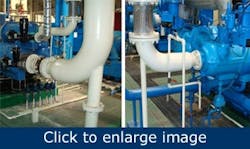
Figure 6. Intake air piping to these centrifugal compressors uses pipe size that is larger than the intake flange. Note the pipe support to floor, the lack of weight on the compressor flange, the condensate drain on intake pipe low point, and the stainless steel wire flexible connector.
Stainless steel inlet piping is an excellent material for large diameter, low pressure inlet air, as long as it’s installed properly and the inside is properly cleaned. Also, there are many grades of thermoplastic material suitable for inlet air piping. I recommend either stainless steel or proper thermoplastic type material for inlet piping in lieu of galvanized piping. Extruded aluminum alloy will work well but, depending on circumstances, might not be the economical choice.
Extruded aluminum alloy tubing can be assembled easily with hand tools to bring a great deal of flexibility to an operating air system or subsystem. This approach is particularly effective for work areas that might have to be rearranged on a routine basis.
Discharge piping
This side of the compressor has more complex considerations. The discharge air can be at 250 °F to 350 °F (for centrifugal, oil-free rotary screw and reciprocating units), or from 200 °F to 220 °F (for lubricant-cooled rotary screw compressors). The pipe must be able to withstand those temperatures and any oil or condensate that might be highly acidic. Even if there’s an aftercooler to drop the temperature to 100 °F or less, consider the consequences if the aftercooler failed.
Air condensate tends to be acidic. In oil-free compressors, such as centrifugals and oil-free rotary screw, it’s usually particularly aggressive without the oil to neutralize it.
Interconnecting piping
Its purpose is to deliver compressed air to the filters and dryers and then to the production air system with little or no pressure drop, and certainly with little or no self-contamination.
{pb}Regardless of the thermoplastic pipe manufacturer’s claims, we never recommend any non-metallic material for interconnecting piping and rarely for distribution header piping. Most of these materials carry cautions about not being exposed to temperatures greater than 200 °F and avoiding any type of oil or lubricant. We never recommend any type of above-ground nonmetallic or PVC piping for air or gas at any pressure.
Here again, stainless steel or appropriate extruded aluminum alloy is the top recommendation for interconnecting piping between the compressor and the filter and dryers, if the compressed air is oil-free. This material of construction resists corrosion much better than standard Schedule 40 black iron pipe and copper. Here are some other considerations.
- Most jurisdictions allow Schedule 10 stainless steel in lieu of Schedule 40 black iron.
- For a given diameter, stainless steel is much lighter and easier to handle, which usually reduces installation labor cost.
- For welded connections, stainless steel usually requires one bead, while black iron usually requires three beads (weld, fill and cover). This also reduces labor costs.
- Stainless steel doesn’t seal well when threaded. It performs much better with grooved connections if welding is impractical.
- In sizes 6 in. and below, extruded aluminum alloy offers the same features at a probable lower installed cost. It also brings great flexibility.
Distribution piping
The objective of a main header is to transport the maximum anticipated or projected flow to the production area and to provide an acceptable supply volume for drops or feeder lines. Modern designs consider an acceptable header pressure drop to be zero psi.
The drops and feeder lines deliver the maximum anticipated flow to the work station or process with minimum or no pressure drop. The line should be sized for near-zero loss. Of course, controls, regulators, actuators and air motors at the work station or process need a minimum inlet pressure to be able to perform their functions, thereby introducing some pressure loss.
Table 2 and Table 3 summarize some of the pros and cons for each type of piping material.
