See compressed air leaks with acoustical imaging
Traditional measuring tools
Most people have some quite sensitive leak detectors growing on both sides of their head, but normal human hearing is not very practical in a noisy industrial setting. The slight hissing sound produced by a gas leak is quickly washed out by the loud process and machinery noises in a busy plant. Therefore, the naked ear is near useless except for detecting very large leaks.
Quite a few years ago instrumentation manufacturers discovered that gas escaping from a pressurized area emits high frequency signals that can be picked up by sensitive microphones. This signal, when mixed down to the audible range can be converted to an easily interpreted audible signal, all the while blocking typical low frequency industrial noise.
Using this method even very small leaks can easily be located with leak detector guns, often fitted with directional pick-up horns to help isolate the signals. The leaks are found by waving the detector around and following in the direction of the sound. Once the general leakage area is found then precise locations and sound intensity can be determined by observing the detector readout in decibels. An approximate leakage flow reading can be estimated by lookup table depending on the sound intensity and distance to the detector.
The exact leak location is usually identified by changing the leak detector tip to a narrower one, or feeling around the pneumatic components to identify the leaking part. These methods are problematic if the leak is located in a location where hands and fingers are not allowed, such as on pinch points or moving machinery behind safety barriers.
Sometimes the leaks can be located on a high ceiling or near the tops of bins, which are not always readily accessible, making identification of the leaking part difficult if not impossible. A sound may be heard in a general direction, but the operator will not know exactly where or on what the problem is located.
See compressed air leaks with acoustical imaging
Acoustical imaging detection—A new way
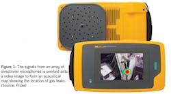
As the general processing power and sensitivity of typical instrumentation grew, some manufacturers discovered that leakage detection could be done with not one, but many sensitive directional microphones. For example, the signals from an array of 64 highly sensitive microphones can be used to detect the sound intensity and the direction of the target leak. And, if the instrument has an on-board video camera, a map of the sound can be overlaid onto the image to give the operator a precise view of exactly where the leak is located (see Figure 1). The instrument processing power can also be used to determine the distance and sound intensity, so that an approximate leakage flow can be calculated automatically. The images are stored in the instrument memory with location identifier and classification tags so the leaks can be prioritized and then found again by repair crews.
One of the big benefits of this type of detection is that the leaks can be identified a significant distance away, in locations that are hard, or even dangerous to access. The sound emitted by the leakage will penetrate cage style safety barriers, keeping the operators well back of hazardous rotating equipment, but close enough to identify specific components.
Practical experience—Wood products company
Recently, an acoustical imager was used to conduct a leakage and end use assessment at a large wood products company. This complex industrial site had thousands of compressed air fittings installed on hundreds of process machines. The production processes ran 24 hours a day, 7 days per week with production taken down occasionally for only short time periods for maintenance. For this reason, it was difficult to schedule the assessment in a practical way during production downtime.
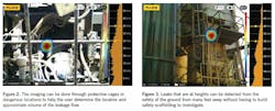
The plant produces large sheets of building material from raw logs. The input to the process waferizes the logs using large cutting disks. The production area is a hazardous location containing a myriad of dangerous pinch points and other areas where out-of-control logs can jump off the conveying system; these risks can easily injure personnel, therefore almost all areas are partitioned off using strong safety cages. This arrangement presents a problem to traditional ultrasonic detection because, while the leakage can be heard somewhere in a certain area, the precise location is very difficult to identify with a traditional detector. Acoustical imaging, on the other hand allows the operator to see through the barriers and locate the offending component (see Figure 2).
Some of the very large leaks identified in this plant were on components that were within caged areas, but on equipment that would not have been pressurized during production shutdowns. For example, some hold-down clamps on the large waferizers are only active when the lumber is being processed. If leakage detection was done during non-production times, then these very significant leaks, caused by the failure of some quick exhaust valves, would have been missed.
The imager also came in handy in identifying leakage at heights. Large leaks, even hundreds of feet away, can be detected simply by scanning the area and identifying the tell-tale colored spot on the video screen (see Figure 3). The assessment uncovered about a half dozen leaks in compressed air fittings along the facility roofline and in outdoor equipment. These items are quite difficult to reach for close inspection; safety rules for working at heights in the plant would have required considerable effort and time expense to arrange for a detailed inspection of each leak using traditional detection methods.
The acoustical imager was also very useful in helping identify some particularly troublesome end uses. During the course of normal leak detection, the microphones also picked up compressed air usage from items that were not leaks but were contributing to wasted flow and unnecessary cost. These types of end uses are often called “inappropriate uses” because they can often be powered by something other than 100 psi compressed air. Some items detected were blowing nozzles (homemade blowers that were simply pipes with holes drilled), bearing cooling, and open condensate drainage points (cracked open valves).
One application detected was a compressed air fitting welded to a sawdust pick up duct, where the compressed air was used to prevent excess material from clogging the duct. The detector is also useful in that it can detect vacuum leaks in ducting. A quick inspection showed that the pickup ducting had a large leak that was reducing the flow of air in the ducting, perhaps the reason for the addition of the compressed air blowing.
A total of 150 cfm of compressed air leakage and inappropriate uses were found during this assessment, about the equivalent of a 40 hp compressor. Estimated cost for this waste is about $26,000 per year at $0.10 per kWh.
No downtime for assessment
Overall, we found that the use of a visual imager improved the efficiency of the leakage assessment, cutting the time required significantly. Since the device could be used during production times, more leak points were found than when leakage is done during non-production times. And various leaks were efficiently found, all the while keeping the assessment personnel safely behind protective barriers. This type of instrument is definitely a new cutting edge tool to be considered for compressed air leak detection.
This story originally appeared in the February 2022 issue of Plant Services. Subscribe to Plant Services here.
About the Author
Ron Marshall
Ron Marshall first developed his skills as an industrial compressed air systems expert at Manitoba Hydro, where he worked for 38 years, supporting more than 600 energy efficiency projects. He now operates his own compressed air energy efficiency consulting firm where he provides technical advice, system auditing, and training. Ron is a level 2 instructor with Compressed Air Challenge and conducts training internationally. Contact him at [email protected].Want to learn more about compressed air? We would suggest sending key staff to one of our Compressed Air Challenge seminars to help them learn what is possible. To learn more about upcoming training opportunities visit the CAC calendar at https://www.compressedairchallenge.org/calendar.


