Why permanent magnet motors and reluctance motors are finding increased industry application
Those familiar with industrial electric motors have heard “DC is dead” for decades as advances in variable-frequency drive (VFD) technology for AC squirrel cage induction motors (SCIMs) seemed destined to replace their DC counterparts in every conceivable application.
But just as DC’s demise was greatly exaggerated, so too is the prospect of successor technologies replacing the installed base of SCIMs any time soon – whether for new applications or replacement motors. Still, it’s wise to recognize that change is coming, and that two of the newer technologies are already in common use – permanent magnet motors and reluctance motors.
Permanent magnet (PM) motors
PM motors fall into two basic categories: those that start across-the-line, and those that require a VFD. Both types may have a salient (pole projections) or a non-salient (smooth surface) rotor, and either surface permanent magnets (SPM) or interior permanent magnets (IPM).
PM motors are significantly more efficient at low-speed operation than SCIMs, and normally do not require forced/separate ventilation to operate in that mode. Typically, they are also about one frame smaller than an SCIM of comparable rating, so they weigh about 1/3 less and occupy up to 3/8 less volume.

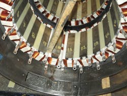
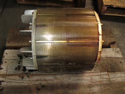
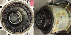
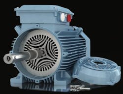
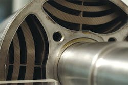
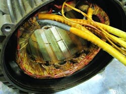
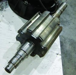
Hybrid permanent magnet (HPM) motors. The HPM is a synchronous variable-speed motor that a European manufacturer introduced about a decade ago, first for compressor applications and later for cranes. Powered from a VFD, the HPM combines elements of switched reluctance (the magnetic equivalent of electrical resistance) and permanent magnet rotor motors. For example, its stator has concentrated salient poles like a switched reluctance motor (Figure 1), while its salient pole rotor consists of permanent magnets (Figure 2). Owing to its unique design, it produces less heating than conventional SCIMs.
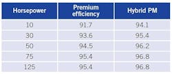
The HPM has a higher torque per input watt ratio than most other PM motors, and nearly constant output torque with less than 1% ripple (percentage difference between maximum and minimum torque over one revolution). Besides being more efficient than a premium efficiency motor of the same rating (see Table 1), it maintains that high efficiency over its operating speed range. Due to its simple design and low starting current, it also can be rated for unlimited starts.
Across-the-line start PM (LSPM) motors. Commercial LSPMs operate at synchronous speed regardless of load and typically can handle a maximum load inertia of about 30 times the motor inertia, which is enough for most industrial applications. A major disadvantage of these motors is their violent starting “kick,” which can accelerate wear of the motor and load bearings, especially in applications with frequent start/stop cycles.
LSPMs are well suited for pumps, fans, compressors, and similar applications, where torque is a function of the square of the speed. They also can be used for conveyor applications due to the low inertia, provided that the starting torque is sufficient. LSPMs are less suitable for hoist drives, elevators, and other applications where overloads can occur and lead to loss of synchronization.
LSPMs have a three-phase stator winding (like conventional SCIMs) and an aluminum rotor cage with internal permanent magnets. They start and accelerate connected directly to the line without the need for a VFD. They also are available in the same frame sizes as conventional SCIMs.
What makes LSPMs capable of across-the-line starting is the addition of a squirrel cage (bars and end rings) winding to the PM rotor (Figure 3). That winding supplies current during starting, causing the motor to develop torque as the rotor accelerates to near synchronous speed. At that point, as with a conventional synchronous motor, the magnets “pull” the rotor into synchronism with the stator’s rotating magnetic field. Because there are no electrical resistance losses (i.e., the current is zero) in the aluminum rotor cage at synchronous speed, LSPMs are more efficient than comparable premium efficiency (IE3) motors.
Although these motors are designed for across-the-line operation on utility (sine wave) power, they can provide excellent performance when supplied from a VFD running in scalar (constant volts/Hz) mode. Therefore, they can replace conventional SCIMs powered by VFDs – i.e., by using the existing VFD.
Low-speed high-torque (LSHT) PM motors. Common applications for LSHT PM motors include cooling towers, paper drive machines, and slurry pumps that operate at low speeds. Slurry pump motors, for example, typically operate in the range of 200-600 rpm, with power ratings from about 40-2,500 hp. Cooling tower drives (Figure 4) commonly run at 100-500 rpm, with typical power ratings from about 10-300 hp.
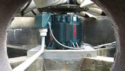
LSHT PM motors are well suited for such applications. Besides their highly efficient synchronous motor design, they improve system efficiency by eliminating the need for gearboxes and couplings to achieve low speeds. This also decreases installation, maintenance, and operating costs while reducing noise levels and the possibility of oil leaks.
LSHT PM motors, however, have lower pullout torque than SCIMs with equivalent ratings, so they must have 20-30% greater pullout (maximum sustainable) torque than the application requires. These motors also have limited short time overload capacity.
The two rotor technologies commonly used for LSHT PMs are surface permanent magnet (SPM) and interior permanent magnet (IPM), with IPM motors being less susceptible to demagnetization at high temperatures and costing less to manufacture.
- Surface permanent magnet (SPM) motors – SPM motors (Figure 5) must operate on a VFD that is programmed to control the permanent magnet flux of the PM synchronous motor. At least one manufacturer offers these motors in power ratings up to 3,350 hp, and in speed ranges of 0-220 rpm up to 0-600 rpm.
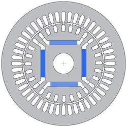
- Interior permanent magnet (IPM) motors – Motors with interior permanent magnet (IPM) rotors can provide exceptionally high efficiency. The PMs are embedded in the rotor structure (see Figure 6) rather than being mounted on its surface (SPM). IPM motors can be supplied from a VFD, but the drive requires special software.
In the past, IPM motors flourished in applications where productivity trumps efficiency, such as CNC machines or machine tools. They also were used in some electric and hybrid-electric vehicles like the Toyota Prius. Now they are gaining ground as general-purpose motors to improve efficiency in a broad range of industrial and OEM applications.
For example, one manufacturer combines a laminated stator frame with an IPM rotor with impressive results: 400 hp IPM rotor motors have tested at up to 98.3% efficiency, as compared with 96.2% efficiency for equivalent premium efficiency motors.
Reluctance motors
The second part of this article covers two types of reluctance motors: synchronous and switched.
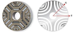
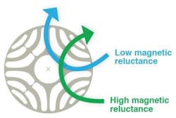
Synchronous reluctance motors (SynRM). A synchronous reluctance motor (SynRM), has a stator winding like that of a conventional SCIM. But its rotor is designed to provide the least possible magnetic resistance in one direction (direct axis d) and high magnetic resistance (i.e., reluctance) in a direction half a pole pitch away (e.g., 45 mechanical degrees for a 4 pole machine) at quadrature q (Figure 7). Torque is produced as the rotor attempts to align the magnetically conducting direction d to the stator’s magnetic field (Figure 8).
When used with a VFD for speed and torque control, SynRMs (Figures 9 and 10) provide large energy savings in applications such as pumps and fans. These motors characteristically provide low torque ripple, low vibration, and consequently low noise levels.
SynRM rotor designs are optimized for use with a VFD, so the power output of a given frame can match that of a SCIM yet have higher efficiency. Further, no currents are induced in the rotor, resulting in cooler operation that extends the life of lubricants and bearings. SynRMs are particularly suited for industrial applications that do not require high speeds nor experience heavy overloads; and due to their high efficiency, they are increasingly available for variable-speed pumps. In the future, adding PMs to the SynRM rotor could further increase efficiency. At least one manufacturer is working on this objective for 1.5-20 hp applications at speeds of 1,000-4,000 rpm.
Switched reluctance motors (SRMs). The SRM design dates to the early 1800s. Not surprisingly, however, no control circuits were available at the time to make an SRM practical. The modern SRM came about in the late 1900s with the advent of electronic controllers.
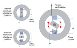
The SRM is a relatively simple machine, with salient pole windings in the stator and steel laminations in the rotor. When current passes through one of the stator coils, the rotor tends to align with the excited stator pole and generates torque. Thus, energizing a stator phase coil produces a single magnetic field that attracts the rotor to its minimum reluctance position, producing reluctance torque (Figure 11). The direction of torque generated is a function of the rotor position with respect to the energized phase.
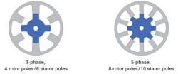
The SRM controller synchronizes the excitation of each phase with the rotor position to produce a continuous torque. Common values for the number of phases in an SRM stator are 2, 3, 4, and 5 (Figure 12). Although the number of rotor poles is often twice the number of stator phases, that is not a design requirement.
The concentrated windings on the salient stator poles (Figure 13) have much shorter end turn lengths than conventional induction motor windings. This reduces the average turn length and, consequently, the winding’s resistive power losses. The rotor poles (Figure 14) do not have any conductors or permanent magnets; and the large air spaces between poles reduce the rotor inertia, sometimes by more than 50% compared with a conventional squirrel-cage rotor. That, in turn, increases the dynamic response to changes in speed.
The simplicity of construction carries with it the promise of relatively low cost that has fueled interest in SRM technologies in recent years. One disadvantage of SRMs, however, is they cannot operate directly from an AC supply line and therefore require a VFD. Other potential drawbacks are that they require a shaft position sensor, tend to be noisy, and have relatively high torque ripple.
Among the applications making use of SRMs more recently are variable-speed compressor motors, for which some compressor manufacturers have used HPM motors. Given their large breakaway and overload torque capability, SRMs are also suitable for such applications as motion control in printers and traction in off-highway equipment. They also may have a future in automobile technology if they can overcome the drawbacks of acoustical noise and torque ripple.
Conclusion
This article highlights some of the newer electric motor technologies in current use – namely permanent magnet motors and reluctance motors. But with incremental refinements in design, squirrel cage induction motors should thrive for the foreseeable future, alongside emerging motor technologies that will present exciting opportunities to improve energy efficiency and reliability.
About the Author
Thomas Bishop
EASA
Tom Bishop, P.E., is a senior technical support specialist with the Electrical Apparatus Service Association and has more than 30 years of hands-on and engineering experience at electrical machinery manufacturing and apparatus service firms. Bishop has authored dozens of technical articles and papers and presented numerous seminars on electric motor application, maintenance, and repair. In addition, he is chairman of EASA’s Technical Services Committee and a principal member of the National Fire Protection Association Electrical Equipment Maintenance Committee (NFPA 70B). Contact him at [email protected].