Discover the true reasons for seal failure
A mechanical seal leaks. The seal is replaced. The new seal leaks. That seal is replaced. Does this sound familiar?
The expected life of a mechanical seal that is appropriately selected for an application and is properly installed and operated should perform until equipment failure. So why are seals that operate weeks or months being casually discarded and replaced without understanding why they failed? Is there another way? The answer is to let the failed seal tell its story during a mechanical seal analysis, which is offered by some seal manufacturers as a service free of charge.
Why do some plant teams fail to take advantage of an analysis?
However, simply tossing the mechanical seal is not the answer. With many seal failures, the mechanical seal acts as a fuse that fails because of an overload or some other problem in the pump system. Seals that are not evaluated to determine the specific cause of failure continue the endless cycle of premature failure because the real reason for failure is never addressed.
What are the benefits of mechanical seal analysis?
Many problems with a system may be discovered by investigating a failed mechanical seal. The story of what the seal experienced during operation, before it failed, can be revealed. An analysis can determine or confirm:
- if there is any misalignment or other mechanical problems in the pump system
- if the seal is suited for the application
- if the seal was installed incorrectly
- if the environmental controls were set up and operated correctly.
Correcting the problems identified following a seal failure analysis may have a huge impact on a plant. Several improvements may be realized, including:
- optimized operating conditions
- reduced downtime
- best possible life from equipment
- improved performance
- decreased maintenance costs
- increased ROI.
What information or materials are needed for an analysis?
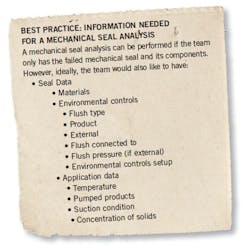
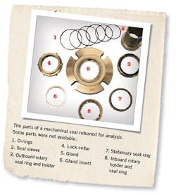
The mechanical seal must be sent to the team who will be analyzing it. Other information the team will need varies (and of course they would always like more data if possible). Some information that the team would prefer to have, in addition to the failed seal or its parts, is shown in the figure.
The team would also like to know how long the seal operated after startup. For example, did it leak immediately upon startup? Did leakage improve after the seal operated for some time? This information may help the team gain insight into the different failure modes.
Failure mode clues
Seal damage types are failure clues. Each symptom or clue can mean a lot of different things based on:
- where the component is installed in the seal
- where the irregularity is found on the component
- how severe the damage is
- irregularities present on other parts of the seal.
For instance, a stationary seal face has a crack originating from the drive pin slot. Also, sticky product residue has adhered to the face. This crack means something different than a stationary seal face with a crack located at a different position and product residue that is fairly clean and not tacky.
Both cases would look the same on a table listing damage. However, the cause of failure would be very different.
In the first example, the crack was caused by the product attempting to adhere the rotary and stationary faces together. This adhesion caused increased torque on the stationary pin and the seal face cracked.
In the second example, the crack was likely caused by impact. This indicated that the seal was not installed properly. Many different symptom combinations can reveal multiple failure modes.
Case study
An automobile manufacturer was operating a centrifugal pump moving e-coat, which is used in the painting process. A multiple, cartridge-mounted, rotary mechanical seal was installed on the process. The seal failed, and the manufacturer sent the failed seal to a seal manufacturer for analysis.
Other than the seal, the team had only a little information about the application and failure. Examining the seal the team found on each:
- inboard rotary seal ring: chips, cracks, and product residue
- inboard stationary seat ring: cracks, thermal markings, product residue, and grooves
- outboard rotary seal ring: chips and grooves
- outboard stationary seat ring: thermal markings, product residue
- inboard rotary seal ring holder: product residue
- outboard rotary seal ring holder: product residue and rubbing
- sleeve: product residue and rubbing.
In addition to this evidence, the inboard and outboard seal faces had visible wear tracks. Each face’s width was 0.142 inch. The inboard face’s wear track was 0.141-inch-wide, and the outboard’s width was 0.129 inch. The inboard and outboard wear tracks were highly nonconcentric, which was also noted on the seal failure analysis report.
The story
The team with the evidence and their knowledge had enough data and evidence to determine the seal’s story and ultimate fate.
- Read "Practical pumps and seals"
The environmental controls for the seal were not adequately set up and operated for the application. The flush pressure was not high enough, which allowed the product to migrate between the seal faces. This product was tacky, and the faces adhered to one another during shutdown. When the pump was restarted, the torque created from the adhesion of the faces cracked the inboard stationary seat ring and caused the set screws to slip. This prevented the rotating components from spinning with the shaft, causing the seal to leak.
Corrective action
The main reason to have a failed mechanical seal analyzed is to ensure that the problems that caused the seal to fail are corrected. In this application, the team made a couple recommendations for corrective action.
The first one was to ensure that the flush pressure was set high enough. The suggestion for this application was to set the flush fluid at 15 psi above the maximum stuffing box/seal chamber pressure.
Product may have contaminated the flush fluid. Ensuring that no product entered the flush system was recommended as well.
Jack Ferguson is a seal reliability engineer with Sealing Equipment Products Co. Inc. He is a recent graduate of Clemson University with a degree in mechanical engineering, and may be reached at [email protected].