How to select the right centrifugal pump

During my career, I have coached numerous new engineers in the selection of centrifugal pumps for process applications. On many occasions, and after years of seeing the costly results of pump theory knowledge gaps, I found that engineers get caught in selection traps that have resulted in less than ideal pump selections. I eventually realized that the root cause of the poor pump selections was a lack of training in centrifugal pump hydraulics basics, and how hydraulic design parameters can dramatically impact a pump’s life cycle costs.
This article is an excerpt from Perez' new book, How to Select the Right Centrifugal Pump—A Brief Survey of Centrifugal Pump Selection Best Practices, published by AuthorHouse and available now from Amazon.com, Barnes and Noble, and AuthorHouse.com.
Choosing a centrifugal pump from the countless options available can be daunting, but someone has to make the decision. Many factors, such as the required flow, differential pressure, and suction conditions must be weighed against the capital costs and cost of energy for the pumps considered. To determine the right pump, you must consider the overall cost of ownership, which includes capital cost, operating costs, and maintenance cost. What good is a low cost pump if it is inefficient or is costly to maintain?
My selection methodology focuses mainly on hydraulic design considerations but also touches on mechanical design details, including key hydraulic deign parameters, such as specific speed (Ns) and suction specific speed (Nss) , NSPHa, NPSHr, and NPSH margin ratio. Analyzing these basic hydraulic parameters allow you to quickly determine if a centrifugal pump makes sense for your particular application. If you do decide a centrifugal pump will work for your application, then you need to be able to evaluate the various bids returned by pump manufacturers.
The importance of system head curve
Every pump manufacturer would like to supply the perfect pump for every application they quote. However to do this, the manufacturer requires the future pump user to provide them with an accurate system head curve that describes the capacity and head needed for your operating conditions. In this section, we will define what a system head curve is, why they are important, and how they are generated.
[javascriptSnippet]
A system-head curve is an analytical or graphical representation of the relationship between the flow and the hydraulic head requirements of a given piping system. Hydraulic head requirements are related to the suction head, the discharge head, and the hydraulic head losses of the piping system. Since hydraulic head requirements and losses are functions of the flowrate, size and length of pipe, as well as the size, number and type of fittings, each system head curve tends to have a unique shape.
Normally, at least one point on the system curve is given to pump manufacturers in order to help them select the pump properly. However, it is highly desirable to graphically superimpose the entire system curve over the head-capacity curve of the pump in order to better understand the interactions between the pump performance curve and the system head curve. By definition, the intersection of the pump performance curve with the system head curve defines the operating point of the pump and piping system. Once the system curve is defined, we can plot various pump curves on top of the system curve and hopefully select one that matches the process needs. Without this system curve, there is not much of a chance of coming up with the right pump.
To create a system curve, we must first plot the desired capacities against the required head over the total anticipated operating range of the pump. The head will be measured in feet or meters and the capacity will be measured in gallons per minute or cubic meters per hour. The general equation for a system curve is given by the following equation:
Hsystem= (Pdownstream - Pupstream) + Elevation + All line losses
Putting this equation in words, we would say that the system head is the sum of (1) the difference between the downstream pressure and the upstream pressure; (2) the elevation difference between the downstream liquid level and the upstream liquid level; and (3) all the line losses. For the remainder of this article we will use the following shorthand version of the equation:
Hsystem = (Pds - Pus) + Hstatic + L
Hstatic is defined as the vertical distance from the surface of the liquid in the suction tank or pit to the level of the liquid level in the discharge tank. Hstatic can be positive or negative.
As the liquid flows through the piping and fittings, it is subject to the friction caused by the internal finish of the piping, restrictive passages in the piping fittings, and any additional hardware that has been installed in the system. The resulting "pressure drop" is described as a "loss of head" in the system, and can be calculated from graphs and charts provided by the pump and piping manufacturers.
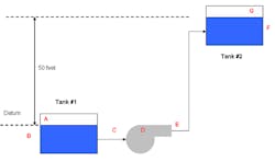
Refer to Figure 1 as we go through a simple system head calculation. Here we have a pump taking suction from Tank #1 (Pus = 0 psig) and moving to Tank #2 (Pds = 0 psig) that has a liquid level that is 50 feet higher than the level in Tank #1. If we assume that the piping losses total 25 feet at 500 gpm, let’s determine the system head requirements:
Hsystem = (Pds - Pus) + Hstatic + L= (0-0) +50+25=75 feet
Keep in mind that the piping losses here only apply to a flow of 500 gpm. In reality the piping losses are a function of the flow rate, and therefore vary with the flowrate.
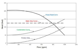
Figure 2 depicts the three basic types of system curves:
- Static-only system curves – an example of a static-only system is a pumping system where a pump is pumping from an open pit into an open pit at a higher elevation with negligible line losses.
- Friction-only system curves – an example of a friction-only system is a pump with significant piping losses that is taking suction from an open pit and discharging into an open pit that are at the same elevations
- Combination system curves – a combination system is a pump system with both significant frictional losses and a significant difference in elevation or pressure at the inlet and outlet piping.
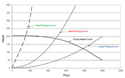
If we combine the system head equation and a centrifugal pump curve, you will get plots similar to what you see in Figure 3. Notice that in Figure 3 that we have one centrifugal pump head-flow curve and three system curves. For simplification purposes all the system curves are friction-only type curves. There is a small piping curve, ideal piping curve, and a large piping curve.
As stated before, the intersection of the pump head-flow curve and the system head curve is the point where the pump will operate. If a “small piping system” is installed, the pump will operate in the low flow region of the pump curve; and if a “large piping system” is installed, the pump will operate in the high flow region of the pump curve. However, if the “ideal piping system” is installed, the pump will operate at an ideal flow region, which is near its best efficiency point.
Normally the system curve is defined by the anticipated process conditions and tends to be set in stone once the process design step of the project is completed. It is the designer’s job to take the system curve information and attempt to match a pump to the piping system. However, to select the right pump, we must have confidence in the system head curve, which is why it is a good idea to understand how system head curves are created and how they are affected by changes in process conditions. Once you clearly understand the shape of your system curve, you can begin choosing the right centrifugal pump to match your hydraulic requirements.
Remember that given the right pump suction conditions, centrifugal pumps always pump somewhere on their curve. The shape of the pump curve will generally be determined by the specific speed number of the impeller. The manufacturer generates their curves at a specific RPM. If you are using a variable speed drive, remember to adjust the curves to match your actual pump speed. You can use the pump affinity laws to approximate the expected performance at the actual pump speed. In addition to the specific speed parameter, the manufacturer can select impeller diameter, impeller width, and pump RPM. You also have the options of operating pumps in series or parallel or selecting a multi-stage pump to meet your hydraulic needs.
The key to reliable pump operation is to ensure the pump and piping system are well matched to allow operation as close to the best efficiency point (BEP). To guarantee you have a well-matched pump and piping system, you need to check and double check your system head calculations to confirm that all factors were considered and calculated properly. Your selection will only be as good as the system head equation and the manufacturer’s pump performance curve.
Final words of advice
To successfully select the perfect pump and pumping system, the pump engineer must look at the whole picture, which includes the suction piping system, the process design requirements, the overall goals of the project engineer and the maintenance engineer.

Caution: Do not work in a vacuum. Today, employers highly regard employees that work well in team settings. We all need to work together and pull together—hopefully all in the same direction. I am hoping this pump analysis calculator will enlighten and encourage readers to better understand their pumps and select their pumps for the right reason. By thinking like a pump designer you will be better equipped to:
- Develop better pump specifications.
- Talk to the suppliers of your pumps with the goal of improved pump selection.
- Select the best pump offered during the pump bidding process.
The time you invest on the front end of the pump selection process will pay healthy dividends in the form of lower life cycle costs and reliable pump operations.
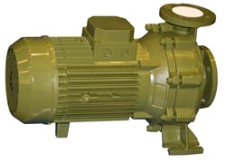
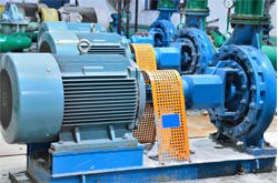
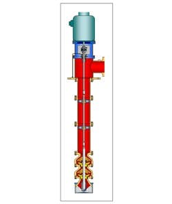
Types of centrifugal pumps
Pumps come in all shapes and sizes to fit the hydraulic requirement of the industry. Here are just a few common designs.