In brief:
- Periodic inspections help ensure that a subcritical power boiler drum achieves its typical 40-year design life.
- A structured, rigorous inspection and documentation procedure captures the details of the drum’s current condition.
- The inspection report forms the basis for decisions about the boiler maintenance program.
As an integral component of a viable boiler maintenance program, the internal visual inspection of the boiler drum, or crawl-through, is a mandatory part of the annual boiler condition assessment program.
In the past, typically plant engineering, maintenance, or the boiler manufacturer’s field representative performed this inspection. However, because of operating and maintenance costs and fewer trained in-house inspectors, many boiler owners elect to allow the annual boiler operating permit inspection to be conducted by the authorized inspector or jurisdictional inspector as a substitute for their assessment inspection.
Because the authorized or jurisdictional inspectors typically are given a limited amount of time to perform a drum crawl-through, a comprehensive assessment inspection is normally not performed during the life of the boiler. To correct this situation, the following approach provides in-house inspection personnel with a detailed strategy for subcritical boiler drum assessment inspections.
Safety
The boiler drum is considered a confined space. As a result, any interior inspection must meet OSHA 1910.146 requirements for entry permits, lock out/tag out, atmospheric monitoring, and an outside attendant.
Boiler drum clearance verification requires that the inspector make a visual inspection to confirm that any system moving liquids or gases into and out of the drum has been isolated (closed), secured, and tagged to prevent operation while the inspector is inside the drum. Only after experienced personnel have checked and verified that clearances are hung and the interior atmosphere is safe can the inspector enter the drum.
Inspection orientation
Before entering the drum, the inspector should determine the drum’s physical orientation for referencing observations made during the inspection. Usually, the drum doors are referenced to a compass direction (north, south, east, or west), and the drum is divided into five sections:
- drum head at entrance
- end of shell
- shell
- end of shell
- drum head at exit.
Additionally, all observations should also be referenced to the drum’s top, bottom, left, or right side. Interior components — steam separators, piping, and chevron scrubbers — should be referenced by sequential numbers starting at the drum’s entrance and continuing toward the drum’s exit.
Inspection equipment
The following equipment should be available for the crawl-through inspection:
- large flashlight (50 lumens or more)
- paint marker or pen (white or black)
- 3-by-5-in. spiral-bound notebook
- digital camera or 35-mm disposable camera with flash
- pens or pencils (minimum of two each)
- small, high-intensity flashlight for backup.
The observations written in the notebook should correspond to the sequence of photographs taken during the inspection. The inspector also should take a picture of the drum’s manway before entering the drum. This signifies that all subsequent pictures will be unique to that particular drum inspection. This becomes extremely important if the inspector uses the same camera to document crawl-through inspections of other boiler drums.
Interior drum head inspection
Before entering the drum, the inspector should examine the entry door for indications of over-temperature (black or dark blue metal color), water stains at the bottom of the door (gasket leak), and loose, unserviceable, or missing door hardware. Then inspect the door gasket face both by sight and touch for any gouges, cuts, and rough spots.
[pullquote]After entering the drum, investigate the gasket face on the door opening (in the head) for gouges, cuts, and rough spots, again, by using both sight and touch. Pull the door away from the drum’s side wall to examine the area behind the door for cracks, gouges, and metal delamination. In addition, inspect the door’s support mechanism and its attachment welds at the door and at the drum’s side wall for cracks, porosity, and undercutting. Mark observations with the paint pen and record it in the notebook. Take corresponding photos of each observation before moving to the next area of interest.
The next item to examine is the drum wall penetrations. Check each penetration — bore holes or pipe sleeves for any cracks at the edges of openings, cracks in the attachment welds and any porosity (cluster or linear). The visual inspection should include upper and lower bore holes at the drum’s instrumentation bridle, upper safety valves, and at the drum vents. These openings should be free of debris, cracks, gouges, and appreciable loss of material thickness in the head and the attached piping.
Some boiler drums have an opening for a downcomer pipe in the bottom of the head. Check the anti-vortex screen and attachment welds to the head at the downcomer entrance for serviceability and tightness.
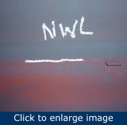
{pb}Figure 1. Mark the drum’s normal water level.
Then examine the piping and piping supports — feedwater, chemical addition, and surface blowdown — for serviceability. Inspect the outer surfaces of the piping for deep pitting — a classic indication of past water chemistry problems; also, inspect connections for broken or loose pipe fittings and loose or missing support hardware. The supports for the interior piping should have enough clearance to allow for thermal expansion during normal drum operation.
Scrutinize the head’s interior surface for cracks, any indications of corrosion (oxygen pitting and iron oxide caps), and evidence of wall thinning (gouges or appreciable loss of wall thickness). Identify the normal water level (NWL) — the red or brown line on the interior surface about half way up the side of the drum — with a paint marker (Figure 1).
Clean and buff to bright metal an area of about 1 sq ft centered on the NWL. This cleaned area helps quantify the amount of material deposited on the drum wall during normal operation. During subsequent maintenance crawl-through inspections, the accumulated water deposits on the cleaned area will give a good visual indication of the quantity of suspended solids present in the drum water and the effectiveness of the water treatment system.
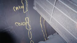
Figure 2. Look for cracks in the heat-affected zone at the head-to-shell weld.
The last and probably the most important inspection in the drum head is a visual examination of the head-to-shell attachment welds. This examination requires that any standing water and debris be removed and the circumferential weld area including the heat affected zone (HAZ) be cleaned on the lower half of the boiler drum (Figure 2).
After cleaning, inspect this weld area closely for circumferential cracking at the edges of the heat affected zone, transverse cracking across the weld, and any porosity (both linear or cluster porosity). If the weld has been subjected to long periods of acidic boiler water, then the weld’s profile will be either indistinct or completely absent.
Interior inspection — shell
The interior arrangement of shell components (steam separators, shields, piping, scrubbers, or dryers) will differ greatly among boiler manufacturers. In most cases, the inspector will find that access can be extremely restrictive or almost impossible between the interior components.
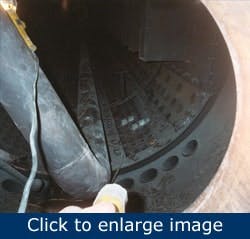
Figure 3. Before starting the interior inspection, remove one or more shell or belly plates from both ends of the drum.
Before beginning this part of the inspection, it is recommended that maintenance personnel remove one or more shell or belly plates from both ends of the drum (Figure 3). This allows for the examination of the space beneath the interior shield plates where boiler water enters the drum and is a collection point for magnetite produced in the waterwall circuits and any other debris trapped in the water circuits.
If possible, the inspector should collect about 1 lb of this deposit for later chemical analysis. The metals found in the drum deposits indicate the component wear in the condensate, feedwater, and boiler water circuits. Furthermore, shield plate removal allows for a visual examination of the tube sheet bore holes. Examine the horizontal and vertical areas between the drum holes (ligaments) for any linear cracks originating inside the holes and running to an adjacent hole; additionally, examine the interior of these holes and tubing for corrosion, wall thinning, pitting, debris, blockage, and tube plugs. Please note that any tube plugs found during the inspection should be located and referenced for later replacement of the failed tube.
Before beginning the shell inspection, look for cracks, porosity, and undercutting at the welds where shields, liners, separators, and scrubbers are attached to the drum wall.
{pb}During the shell crawl-through, the inspector should examine the following:
- steam separators (screen, baffle, turbo, and cyclone) for mounting hardware, tightness, and overall serviceability (often, tightness is determined by rapping on each separator — a loose separator makes a low-pitched “thud” noise, and a tight separator has a high-pitched “ding” sound).
- downcomer nozzles and inlet screens for cracked, broken attachments, porosity and undercutting at the attachment welds
- shield retainers (dogs or fillet welds) for looseness, cracks, and missing or loose cap nuts on the retainers
- shield plate boundaries (there should be no openings or separation between floor and side plates; openings allow water to bypass the separators, causing solid carryover into the superheat steam circuits)
- scrubber and dryer tightness (use same method as used on separators)
- feedwater, chemical addition, and surface blowdown piping connections for serviceability (broken welds, loose, and missing hardware)
- any drum circumferential or longitudinal welds in the drum’s shell and any attachment welds to the drum’s interior surface.
Also, the inspector should number each separator or dryer while performing the crawl-through to specify the physical location to identify discrepancies within the shell.
Inspection report
The final segment of the drum inspection is the inspection report. Its format should be concise, and the observations and recommendation should be easy to comprehend.
The inspector should assign a priority system for qualify the severity of each observation. This gives the boiler’s owner and maintenance staff a way to establish priorities for later maintenance work. The following is an example:
- Priority 1 — Observation must to be addressed now. It should be considered as an emergency repair. Failure can result in lost generation or endanger plant personnel.
- Priority 2 — Observation should be addressed during this outage or can be deferred until next scheduled outage. Failure might adversely affect generation or might endanger personnel as the condition deteriorates over time. Priority 2 observations often deteriorate to Priority 1 conditions.
- Priority 3 — Observation should be monitored during future inspections. Failure won’t affect generation adversely or endanger personnel. Often used for engineering studies.
The prioritized observations need to be matched with a corresponding picture. This provides a visual aid for later finding the discrepancy. The report should follow the same sequence as the inspection — drum head, shell, and other drum head; in addition, the inspector should develop a list at the end of the report of all Priority 1, 2, and 3 observations.
Final observation
|
About the authors David Murphy is Director of Operations at Fluor (www.fluor.com). Contact him at [email protected] and (972) 450-8184. Ed Simpson is Manager of O&M Technology at Fluor. Contact him at [email protected] and (972) 450-4179. |
The average design life for a subcritical power boiler drum is about 40 years. Depending on the mode of operation (cyclic vs. base-loaded), maintenance history, and current boiler drum condition, the remaining safe operational life and serviceability of the boiler drum will require at least one extensive assessment of the drum’s shell and its interior components during its service life. This assessment requires the following maintenance, inspection, and non-destructive examination activities:
- removal of interior components, including shields, separators, scrubbers, screens, and baffle plates
- extensive cleaning of interior surfaces, including nozzle penetration and pipe openings, manways, and circumferential and longitudinal shell welds
- nondestructive examination of wall and head welds using phase array or RT; wet fluorescent magnetic particle (wet mag) for nozzles, drum door, bore holes, tube sheet, and attachment welds
- mapping of the remaining drum wall thickness in selected areas using an ultrasonic thickness gauge at tube sheets ligaments, heat-affected zones at circumferential and longitudinal welds, and locations of previous thinning.
This extensive assessment should be performed at least once in the operational life of the boiler and most definitely after reaching the boiler drum’s design life of 40 years.


