Unique piping design reduces beverage bottler's electric energy bill
A beverage bottling plant had three oil-cooled rotary screw compressors as its primary air supply. One 150-hp class, 750-acfm at 100 psig at 129 kW unit served as base load with two 75-hp class, 360-acfm at 100 psig at 63 kW units as trim compressors.
The average flow during production demand was 700 acfm at 105 psig with peaks to 820 acfm. Production ran 85 hours per week or 4,420 hours per year. Sanitation ran 35 hours per week or 1,820 hours per year. Non-production ran 48 hours per week or 2,496 hours per year. (Compressed air was required during the weekends.)
The air demand during sanitation was 450 acfm or less at 110 psig, and the weekend use averaged 277 acfm with peaks to 410 acfm depending on what maintenance and repair programs were being implemented.
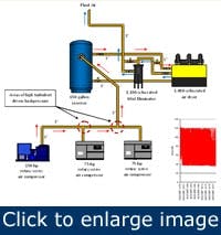
The schematic shown here reflects the basic equipment layout and design. The base load 150-hp class unit feeds a 3-in. copper header from the end and the two 75-hp class trim units come in with 90° entry to the 3-in. header from two opposing sides creating a “dead head.”
The problem
When the 150-hp compressor was able to run base load during production, everything was fine. Usually during the first hour of the production shift, the demand would exceed 150-hp supply, the first trim unit (No. 2) would come on, and the 150-hp unit would now short cycle and average about 50% to 60% load (375 acfm to 450 acfm). The trim unit and the base load unit now run all the time at mostly part load. The plan was for the trim unit to come on line, add air as required, unload, and then turn off. The peak load occurs less than 10% of the time.
[pullquote]Planned operating cfm/kW profile for 4,420 hours per year:
150-hp: 129 kW x 4,420 hours = 570,180 kWh
75-hp: 63 kW x 4,420 hours x .10 = 27,846 kWh
Planned total kWh = 598,026 kWh x .10 kWh = $59,803/year
The actual operating profile
150-hp: 120 kW x .85 = 109.7 kW
109.7 kW x 4,420 = 484,874 kWh
63 kW x 4,420 x .90 = 250,614 kWh
Actual total kWh = 685,488 kWh x .10 kWh = $68,549/year
The sanitation shift used a steady 450-acfm and this was effectively supplied by the 150-hp class unit:
- 45 acfm at 60% flow
- 88% power = 129 x .88 x 2114 kW x 820 hrs/year = 206,606 kWh
- Planned and actual electrical energy operating cost = $20,661/yr
- (206,606 kWh x $.10 kWh)
The weekend shift average of 277 acfm demand only calls for one 75-hp class compressor; however, two units are on almost all the time. As soon as the random demand exceeds the 360 acfm available from one unit, the second unit comes on and both units short cycle at 50% to 60% load. They never reach full blow down and idle therefore, the design idle kW of 20 kW is only 41 kW in the unload short cycle; it was 63 kW at full load. At 50% load as running, you have:
Unit 2: 360 acfm at 63 kW at 2,496 hours x .5 = 78,624 kWh
0 acfm at 41 kW at 2,496 hours x .5 = 51,168 kWh
Unit 3: 360 acfm at 63 kW at 2,496 hours x .5 = 78,624 kWh
0 acfm at 41 kW at 2,496 hours x .5 = 51,168 kWh
Actual total electrical operating energy cost = $25,998/year
(259,984 kW x $.10 kWh)
Total annual operating electrical energy cost = $112,507/year
(259,984 kWh + 206,606 kW + 658,488 kWh = 1,125,078 kWh x $.109 kWh)
The actual electrical operating energy cost far exceeded the projected cost when the system was upgraded and the compressors had to run at a higher pressure of 108 to 110 psig to deliver 80 to 85 psig to the operating system which also did not equal the design criteria. The compressors, controlled by an OEM supplied central air management system, did not seem to be optimizing the compressor alignment relative to the demand.
According to plant management, after reviewing a proposal for a new VSD controlled compressor (100-hp class) that “would probably” correct the problem, called in an independent compressed air consulting company, Air Power USA, of Pickerington, Ohio, to review the entire situation. Air Power USA Inc. (www.airpowerusainc.com) does not sell equipment nor participate in the sale of equipment and installation. As a consulting company, they offer project management and systems design in addition to energy audit and rebate assessment.
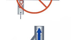
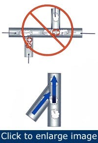
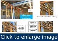
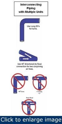
Air Power USA identified the primary problems as “…too small collector header (3 in.) combined with the high turbulence generated by the configured crossing “T” and dead head” (see current piping configuration schematic). There were other suggestions to lower air demand with air conservation projects but as long as this situation continues, the central air management system was not able to control properly as it continued to receive erratic signals and pressure spikes from the high turbulent driven backpressure. The local controllers on each unit were shocked into short cycling. The air compressor control system was not able to effectively translate less air usage into lower input kW in a timely manner.
Reconfigured piping
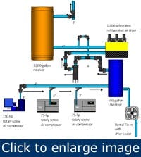
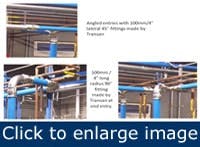
Air Power USA recommended a 4-in. header to replace the current 3-in. and to use directional entry to eliminate the crossing tees and dead heads (see reconfigured piping configuration schematic). Air Power USA also recommended several air saving projects — no loss condensate drains, convert open blow off lines to venturi amplifiers, convert air vibrators with electric and, most important, repair air leaks and continue to pursue an active compressed air leak detection program.
The plant’s compressed air system was plumbed in copper with high temperature solder joints. Air Power USA’s recommendation was to replace the 3-in. header and the 3-in. copper lines to the pre-filter and dryer and over to the “dry” air receiver with a 4-in. header.
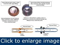
Plant personnels felt this would be expensive in cost of material and, more importantly, it would require three to four days downtime which they did not have. Air Power USA recommended they consider installing the extruded aluminum piping with “reusable” fittings manufactured by Transair. This product has just as low friction pressure loss as copper. In addition, all connections are internally smooth witih “extrernal upset.” The copper pipe used in this facility was internal upset which, even though a smooth material, will create more internal turbulence under most conditions.
The Transair representative came to the plant and developed a complete bill of material with plant personnel and the Air Power USA project support auditor. When all was said and done, the Transair material cost was lower than comparable copper components and/or stainless steel (which also required welding or soldering).
When asked about how long it would take to remove the existing copper pipe and install the new, the field program manager and Transair representative estimated one to two days. “That doesn’t sound possible,” stated the plant engineer. Ultimately, the plant gave the installation team (one field project support manager and three unskilled laborers) 24 hours on a Saturday to get the job done.
After the material was mobilized and the action plan laid out, the complete job was implemented in 10 hours. No welding, no threading, etc. The job came in on time and under budget. The result:
- With a stable header and lower pressure loss, the overall discharge pressure of the compressors was lowered from 110 psig to 90 psig (20 psig, or about a 8% to 10% reduction in kW) and still delivered a stable 85 psig to the production area.
- With a stable header pressure, the central compressed air management system was able to do its job and keep the most efficient air compressed alignment on line considering flow, pressure, timing and individual unit characteristics.
Running the same two production lines, the true results were:
Before the repiping and realignment — Total annual electrical operating energy cost = 1,152,072 kWh — $115,208 / year
After the repiping and reconfiguration — Total annual electrical operating energy cost = 571,400 kWh — $57,140/year
A reduction of 54%
Summary
Modern design and configuration of compressor room interconnecting piping, combined with an economical, efficient, compressed air piping system, reduced the energy cost over 50% to supply the compressed air power/energy at this plant.
Pipe class sizes:
- 16.5 mm O.D. = 1/2 in. ID
- 25 mm O.D. = 7/8 in. ID
- 40 mm O.D. = 1-1/2 in. ID
- 63 mm O.D. = 2-1/2 in. ID
- 76 mm O.D. = 3 in. ID
- 101 mm O.D. = 4 in. ID
For more information, contact Paul Johnson, Parker Legris Transair, at (480) 830-7764 (www.transair-usa.com) or Hank van Ormer, Air Power USA Inc., at [email protected] or (740) 862-4112 (www.airpowerusainc.com).
