Modern industrial centrifugal compressors represent an energy-efficient, effective supply of compressed air. Their advanced designs and manufacturing capabilities offer energy savings opportunities to those who understand how to select and install them. The compressor’s operating characteristics, which some might call “quirks,” represent opportunities to the savvy plant professional.
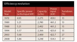
In a recent compressed air review at a large paper mill, we investigated six 500-hp, three-stage centrifugal compressors, all of same model by the same manufacturer and built at separate times during a 30-year interval. The operating curves for these units revealed differing specific power ratings and operating characteristics at 100% full load discharge pressure (Table 1). Much of this improvement in the later versions comes from machining and production processes that work with microns of tolerance instead of the mils used in the past. That capability frees engineers to follow visions that weren’t practical a few years ago. Also, improvements and new technology in electronics, controls, main drivers, inlet guide vanes and the like contribute to overall improvements in basic performance and flexibility.
The improvements in similar-sized standard units offer almost a 15% improvement in specific power from 1970 to 2008, with an accompanying improvement in calculated effective turndown from 15% to 30% or more. About 3% of this comes from basic improvements in standard motor efficiency. If the older motors have been rewound or just lost efficiency because of the condition of the breaker, line or insulation, the overall improvement in specific power might well be higher; perhaps as high as 20% or more. The motor performance should be part of the overall evaluation. (Input kW = power to drive the centrifugal compressor’s motors at rated flow/pressure.)
If you bought your centrifugal compressors in the 1970s through the 1990s, it would be prudent to review the basic performance improvements that are available now. An important factor to consider is the net reduction in electric energy operating costs that your operation will enjoy if you upgrade your hardware. Depending on your application, the dollars can be significant.
Any plant suspecting an opportunity should look carefully at what’s available. Several years ago, a large bottling plant in the southeastern Unites States replaced its 1970-vintage high-pressure (100 psig) and low-pressure (55 psig) centrifugal compressors with units built in 2005. The resulting specific power improvement along with a 25% increase in turndown capability yielded a $600,000 per year electrical energy cost savings ($0.05 kWh, 8,760 hrs per year). The new units cost $600,000 and the total installed cost was $1.2 million, which meant there was a two-year simple payback. Utility incentives further reduced this payback period. This was an effective project spawned from a comprehensive, full-plant compressed air audit.
Turndown and electrical energy
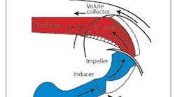
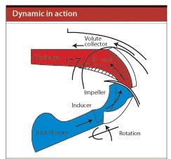
The industrial centrifugal compressor is a dynamic unit that uses a rapidly rotating impeller to accelerate airflow (Figure 1), which then passes through a diffuser section that converts velocity head into pressure head through flow resistance. In the dynamic, or mass-flow compressor, like the centrifugal unit, the power to compress the air is a function of the weight of the air, the flow, volume, temperature, and the head or pressure.
The impeller is the heart of the centrifugal compressor.
The impeller’s design and speed establishes the energy imparted to a pound of air as it passes through the impeller. That energy is independent of inlet temperature, pressure, throttling and other variables. A centrifugal compressor, therefore, delivers a pound of air with a constant expenditure of energy, winter or summer. The volume of inlet air to be compressed varies with the inlet pressure and temperature.
If more compressed air is produced than is needed, the centrifugal compressor must unload (deliver less air) to avoid overpressure. A centrifugal compressor has a maximum pressure it can achieve under specific inlet conditions before the air flow reverses and surges, which triggers a compressor shutdown to avoid damage. This is an oversimplified description of surge; however, each unit has a rise-to-surge limit or maximum pressure. Turndown is the fraction of full-load flow the compressor can handle without experiencing surge. For example, 15% turndown means the unit must run at no less than 85% capacity flow to avoid surging.
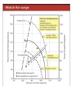
Remember that the surge point varies with inlet conditions (Figure 2). Air density increases at colder temperatures and higher inlet pressure, reducing the volume of inlet air that reaches the maximum mass flow rate. To hold a constant target discharge pressure, the inlet air flow must decrease to avoid “running out on the curve” too far and reaching the stonewall area of potentially unstable operation. The opposite occurs at higher temperature and lower inlet air pressure. The centrifugal compressor can respond to a varying demand efficiently only within its turndown range. Beyond full turndown, the unit responds in one of two ways. Either it blows off excess air and delivers less air but with no reduction in power consumption, or the inlet valve closes partially and operates with blow-off or recirculation at a 25% to 35% power draw with no flow to the plant. This type of capacity control is storage-dependent.
The three curves compare operating characteristics with pressure and flow, including changes in surge point and horsepower requirements without a controlling device in the inlet and discharge piping.
Turndown is another area where modern units are superior to older ones. The greater the available turndown, the more flexible the unit is in meeting varying demand profiles efficiently. Achieving a reasonable turndown of 25% or more in an older unit usually requires using impellers designed for higher pressure and sacrificing lower-pressure operating efficiency. This is still somewhat true today but, in reality, the efficiency difference is much lower. We now have as much as 37% turndown at 5.86 scfm/kW - a solid situation.
Modern inlet guide vanes are much improved over older versions, and are relatively easy and economical to retrofit to most existing units. Inlet guide vanes don’t increase turndown, but they allow the unit to operate throughout the turndown range at or near full-load efficiency.
The data in Table 2 are drawn from a 2,500 cfm-class, 125-psig, three-stage compressor operating in the Midwestern part of the United States and show calculated performance and turndown limits at various times of year. The scfm rating reflects the relative air density and several other factors to establish limitations:
- Effects of ambient temperature and pressure
- Mass flow rate that avoids overloading the motor
- Cooling water temperatures
- Limited maximum volumetric flow rate
These are the effects of inlet temperature and ambient condition on performance and turndown
for a typical three-stage centrifugal 2,500 scfm-class at 125 psig.
With these thoughts in mind, it’s obvious that an effective capacity-control system needs accurate data regarding inlet conditions, power draw and operating temperatures to optimize turndown. This, in conjunction with modern inlet guide vanes, allows the widest possible range of operation at or near full-load efficiency.
Also, the air-management system should keep the units within their turndown ranges, except one that might be in blow-off. There are some effective centrifugal compressor central air-management systems that do this well.
Other efficiency improvements
Select the right electric motor. Be sure it’s large enough to handle the maximum expected flow in the cold conditions. Several years ago in a system designed for the southeastern United States, we used four 500-hp-class, three-stage units with 700-hp motors and an effective central-air-management system. During the nine months of cooler weather, we ran only three units. During the hottest months, we had to run four units most of the time. As a matter of interest, we also used heat of compression desiccant regenerative dryers and held the velocity in the interconnecting stainless steel piping to less than 20 fps, both of which resulted in a significantly lower input electrical energy for desiccant-dried air.
Run the compressor at the lowest effective pressure while avoiding surge. The effect of running most centrifugal compressors at an acceptable lower pressure is an increase in the flow at, or nearly at, the same horsepower draw. The magnitude of this increase is dependent on individual unit performance curves. A unit we audited recently delivered 1,884 acfm at 453 bhp at 135 psig. The same unit at 90 psig delivered 2,074 acfm at 453 bhp - an increase of 190 acfm using the same power. This particular unit has a relatively steep operating curve; another unit might exhibit a much greater flow differential. Operating at the lowest effective pressure might require modifying the piping and ancillary air-treatment equipment.
Upgrade your existing units. Many original equipment manufacturers and some aftermarket organizations offer performance-upgrade packages for older units. In one case, a completely new high-performance compressor package can be set on the old drive train, in effect delivering a new unit a lower cost.
Add new technology. The centrifugal compressor lends itself to significant advances from technology, particularly with electronic controls and variable-speed drives. The electronic controls continue to improve performance with electronic devices that can cycle in milliseconds.
Use high-speed drives. Asynchronous induction motors with magnetic bearings can operate as fast as 60,000 rpm. This drive system eliminates the need for a speed-increasing gear box. The magnetic bearing provides the motor and direct-driven compressor assembly with stable control throughout the operating range. The shaft is supported by a magnetic field resulting in no contact and no wear.
This technology offers up-front advantages:
- No oil anywhere in the drive train
- No startup air required to hold oil back from the compression chamber when a double labyrinth seal is used
- Normal drive train mechanical losses are reduced from between 12% and 17% to between 6% and 9%
- The current lineup is two-stage units that are about 4% to 6% less power-efficient than a comparable three-stage unit. This is more than offset by the savings in mechanical losses.
- Compressors can use the so-called “new impeller design” with good efficiency well below the first critical speed. Most conventional units go carefully past the first critical speed and try to operate below the second or between the second and third.
- Capacity control is achieved with a microprocessor-controlled variable-speed drive. When the demand for air falls and the pressure starts to rise, the drive speed reduces proportionally down to about 25% (or the calculated actual turndown range). If the pressure continues to rise and crosses the adjustable maximum pressure point (usually 10 psid), the unit then goes to no load. The speed falls to idle and the energy draw falls to 2.5% (compared to 25% to 35% or more for conventional units). When the pressure falls to the preset “load in pressure,” the compressor immediately goes to full flow. Every time the unit goes through this cycle, it calculates the actual surge point and adjusts the control accordingly to optimize the turndown capability.
Obtaining the full benefits of this capacity-control system, like every other, requires a minimum volume of effective storage. Depending on the size of the dead band, average flow and piping configuration, this probably will range between 3 gal. and 5 gal. of effective storage per cfm of flow. Effective storage includes all air receivers, equipment and piping inside the dead band range (unload pressure/load pressure). Unlike a positive displacement compressor, there’s no extra energy required to produce the dead band. Running the centrifugal compressor at a higher pressure means lower flow at about the same horsepower. Obviously, if we’re unloading, we don’t need the extra flow.
As presented, this new technology promises a two-stage, oil-free compressor with overall full-load efficiencies equal to most similarly sized three-stage centrifugals and is somewhat better than many two-stage, oil-free rotary screw compressors. The controls allow an effective load/no-load (two-step) operation with a low idle input power of 2.5%. The electronic microprocessor continues to recalculate the actual turndown capability and use it appropriately.
There’s a lot going on in the centrifugal air compressor world. Product and performance improvements are constant. Take a good look at your existing units. A full review or compressed air audit might identify real opportunities for improvement.
Hank van Ormer is owner of AirPower USA, Pickerington, Ohio. Contact him at [email protected] and (740) 862-4112.
Figures: Ingersoll-Rand, F.S. Elliott, Compaire and Cameron Compressors


