Unfavorable market conditions have shut down many plants temporarily. Others have regularly scheduled shutdowns during the year. Maintenance departments frequently take advantage of these opportunities to repair or perform testing that can’t be done when hydraulic machinery is operating. But given the lull in the action, many times the only attention a hydraulic system gets is an oil and filter change.
If those are the only two tasks on your work order, they won’t necessarily increase reliability. You’ll need to perform several other checks and procedures during down periods to boost the odds of gaining system efficiency and operation when production demands are high. The following preventive maintenance checks will reveal other maintenance work that will improve system and machine performance.
Clean the reservoir
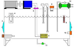
Now is an ideal time to clean the reservoir (Figure 1). Maintenance mechanics and electricians chuckle when I tell them that the reservoir should be cleaned at least once a year. While consulting with a large wood products plant, the mechanic said that the reservoir on one system hadn’t been cleaned since the mill started up 17 years before. Beyond oil storage, the two main purposes of the reservoir are to allow contaminants to settle and to dissipate heat. If the reservoir isn’t cleaned, it’ll act as a heat sink and can cause the system temperature to rise above 140°F, the point at which oil starts breaking down, adding sludge and varnish to the system. If the contaminants aren’t removed from the reservoir, they’ll be drawn into the pump and cause premature failure of the system components. And, of course, be sure to use lint-free cloths when cleaning out the reservoir.
The reliable hydraulic system reservoir needs to be outfitted with specific components.
Key:
1. Reservoir
2. Reservoir heater thermostat
3. Manhole
4. Level indicator
5. Suction line
6. Foot valve/filter screen
7. Level switch
8. Breather cap
9. Temperature indicator
10. High-temperature switch
11. Manual drain valve
12. Water-type cooler
Clean and flush
When you clean the sump, you don’t necessarily need to replace the hydraulic fluid. Unless the oil is severely degraded, all you need to do is run it through a 1-micron filter into a storage tank to remove solid contaminants and water. Then, run the oil through a clean 1-micron filter when refilling the sump.
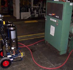
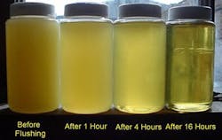
The next step is flushing the lines to the valves and actuators with clean oil. Figure 2 shows the flushing unit we use for this process. Connect the inlet and outlet lines of the cylinders and motors together. If possible, electrically or manually actuate the directional valves to allow the fluid to circulate through the piping. If this isn’t possible, bypass the directional valves by connecting the pressure and tank lines to the actuator’s outlet lines. Use the pump on the machine to circulate the oil through the lines. Connect the flushing unit so it circulates the oil in the reservoir through 1-micron filters. Allow the system to run for as long as possible. Figure 3 shows the purity of the oil for a system before it was flushed, then after one, four and 16 hours of flushing.
Circulate filtered oil from the refilled sump through the system to flush contamination out of the other components.
Other reservoir tasks
An important variable is the reservoir heater setting. Check the reservoir heater thermostat (item 2 in Figure 1) to verify that it toggles on at a minimum temperature of 70°F. A pump mounted on top of the reservoir can cavitate if the oil temperature drops below about 60°F.
Insufficient oil depth can cause problems, so most reservoirs feature two switch settings (item 7 in Figure 1) - a warning and a shutdown. The problem with this configuration is that the difference between the two levels might represent several hundred gallons of oil. Eliminating the warning switch and setting the shutdown at a higher level minimizes the oil loss should a hose rupture.
Next, verify that the breather cap (item 8 in Figure 1) has a rating of about 10 microns. This is the first line of defense against airborne contaminants entering the tank. Depending on the location, the breather cap might need to be changed a couple of times a year. Other options include pressurizing the reservoir with an internal bladder or using a moisture removal-type breather.
High temperature can undo your efforts. Oil starts breaking down at 140°F, but many systems won’t initiate system shutdown until the oil temperature reaches 160°F. If your hydraulic system is operating above 140°F, there’s a problem in the system that might be traced to a cooler malfunction or excessive bypassing at the pump, valves, cylinders and hydraulic motors. Set your high-temperature switch (item 10 in Figure 1) at 140°F to shut the pump off and prevent oil breakdown.
In round terms, the longer you can permit the hydraulic fluid to circulate during the flushing operation, the cleaner it will become.
Now for the system
Heat exchangers need flushing and cleaning. Flush the tubes in a water-type cooler (item 12 in Figure 1) periodically to remove deposits. A mild alkaline solution such as Oakite or a 1.5% solution of sodium hydroxide or nitric acid can be used. If your system uses an air cooler, verify that the fan turns on when the oil temperature reaches about 118°F. Use combs to straighten the fins on the unit if necessary.
Don’t forget pump testing. If you use a variable-volume pump, check the flow out of the case drain line by porting it into a container and using a stopwatch to measure the flow. Make this test with the outlet pressure at maximum. Don’t risk safety by holding the line by hand during this test. Instead, secure it to the container before starting the pump. The normal case flow is 1% to 5% of the maximum pump volume. Vane pumps usually bypass more than piston pumps. If 10% of the maximum volume flows out of the case drain line, replace the pump.
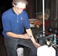
Test fixed-displacement pumps by checking the flow through the relief valve. Turn the pump on and measure the flow rate coming from the relief valve tank line for one minute (Figure 4). Then reduce the relief valve setting to its minimum. There should be less than 10% difference in flow rates between the two tests. If a pump is badly worn, the flow will be considerably less at the highest pressure.
A bucket and a stopwatch can reveal whether a fixed-displacement pump has worn internals.
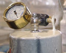
Test accumulators if your hydraulic system uses piston accumulators, install the charging rig and bleed the oil off the top of the piston (Figure 5). With the pump on and the bleed valve open, there should be little or no flow exiting the bleed valve. If the flow is continuous, the piston seals or barrel are badly worn. If the flow ceases, recharge the accumulator to the proper pressure using dry nitrogen.
Test bladder-type accumulators by installing the charging rig on the valve stem. Osmotic pressure forces dry nitrogen through the bladder over a long period of time. If necessary, pre-charge to the recommended pressure.
Look for worn hoses
Check the hoses in the system for the proper length and signs of wear. It’s rare for a hose to burst because the rated working pressure was exceeded. Normally, hoses rupture because of a poor crimp or from rubbing on a beam, another hose or some other object.
If rubbing can’t be avoided, invest in a reel of hose sleeves, which are available from a variety of manufacturers. A hose should not exceed about four feet in length, unless it moves with a machine member. Also, inspect system piping to verify that a hose is included where you connect to a valve bank or cylinder. The hose absorbs the hydraulic shock generated when oil is rapidly deadheaded.
An exception to this rule is that you should use only hard piping when connecting to a vertical or suspended load. Pilot-operated check valves and counterbalance valves are used to hold the load in the raised position.
There should be no continuous flow from the bleed valve on a piston accumulator.
Clamp correctly
Verify that pipes are mounted to structural elements are made using proper hydraulic clamps. Ordinary beam and conduit clamps aren’t acceptable, because they can’t absorb the shock generated in the piping or tubing. Space the clamps about five feet apart along the run and within six inches of the pipe or tubing terminations. Once the system is thoroughly inspected and upgraded, develop a preventive maintenance schedule to make these checks on a regular basis. Many times, no thought is given to the hydraulic system as long as it’s running and the machine is operating. By performing the checks listed here, your systems will operate at maximum efficiency, operate more safely and reduce downtime.
Al Smiley is president of GPM Hydraulic Consulting Inc., in Monroe, Ga. Contact him at www.gpmhydraulic.com, [email protected] and (770) 267-3787.

