In many cases, plant engineers don’t realize — but need to know — how they can use transformers to resolve incidents of voltage distortions that can result from common industrial practices.
Using large numbers of AC and DC electronic motor drives (or other forms of rectifier power control) can cause harmonic voltage distortion and voltage notching. These distortions can lead to malfunctioning drives, or damage to other connected equipment.
A vast number of products are being used to mitigate the effects of current distortions. Transformers can be used, for instance, either singly or in combination, to "cancel" out certain harmonic components, while supplying power to the primary distribution system. Many engineers may be unfamiliar with using "harmonic canceling" transformers and how they differ from standard transformers.
|
View related content on PlantServices.com |
Using transformers to mitigate the affect of harmonics
Before deciding when and how to use harmonic canceling transformers, it’s important first to understand how transformers affect harmonics. Plant engineers have two options in using transformers to reduce harmonics:
Harmonic attenuation.
Harmonic cancellation.
The non-linear currents from two or more three-phase load panels can be phase-shifted from one another through various types of three-phase transformer connections so that their aggregate distortion is less distorted than each of the original’s waveforms. This reduces the distortion of current flowing into the primary power.
Motor drive current distortion can be reduced using filters, 12-pulse or higher drives, line reactors, drive isolation transformers or harmonic canceling transformers. Both line reactors and drive isolation transformers use reactive harmonic attenuation effects to reduce the actual current distortion at the input terminals to the drives. This practice alone can increase the six-pulse drive load by 20 percent or more of service capacity without exceeding guideline distortions. The effectiveness of reactive harmonic attenuation varies, depending on other system characteristics. Careful system analysis is always a good idea before applying any harmonic abatement solution to ensure the intended results.
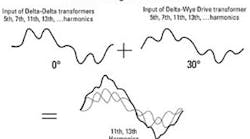
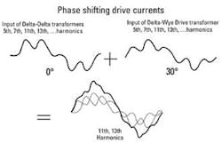
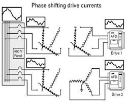
Harmonic abatement using filtering and/or 12-, 18- or 24-pulse drive technology is becoming increasingly popular, but these are relatively expensive solutions. Using transformers for harmonic cancellation can be an attractive alternative, particularly for users who incorporate isolation transformers for their drives anyway. The simplest cancellation method is to provide Delta-Delta connected transformers for some drive power, and Delta-Wye connected transformers for the remaining drives. If the sum of drive loads on each type of drive isolation transformer is balanced, current distortion into the primary system can be reduced significantly.
In some cases, Delta-Delta connected drive isolation transformers are undesirable because the secondary cannot be grounded in a balanced way. Ungrounded power can adversely affect the operation of some drives, and can cause drives to trip on surges and impulses coupled from the primary service. For these applications, Delta-ZigZag connected transformers are available. This zero-phase shift connection acts like a Wye source for the drive, providing a balanced neutral point for grounding. At the same time, they substitute for Delta-Delta transformers, providing the same harmonic abatement when used in combination with Delta-Wye connected transformers serving other drive loads on the same service, as in Figure 4. Of course, when voltage change is not required, the use of line reactors on half the load along with Delta-Wye connected loads on the other half also can be used.
'Harmonic canceling transformer' — a misnomer
Since standard drive isolation transformers can be effectively used as harmonic canceling transformers, the term ‘harmonic canceling transformer’ becomes somewhat ill-defined. In general, that special term is attributed to transformer products with special connections that can address 11th, 13th and even higher harmonics in drive loads. These can be single transformers with multiple secondaries, or sets of transformers feeding multiple loads. The basic principles are the same, except that 15-degree phase shift is required to address 11th and 13th harmonics.
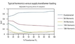
The benefits of this additional step in harmonic reduction are dubious, however, because 11th and 13th harmonic components contribute to less than one-fifth of the total distortion in service entrance currents. The difficulties of obtaining precise balance of loads will almost always leave enough residual 5th and 7th harmonic distortion to minimize the benefit of any higher harmonic treatment. Filtering is a much more cost-effective method for addressing upper order (11th and higher) harmonics compared to special ‘harmonic cancellation’ transformers.
Understanding how to use transformers to remedy voltage distortions can save plant managers time and money. Knowing when to use harmonic cancelling transformers, and how they differ from standard transformers, is the key.


