Contamination of hydraulic and lubricating fluids, as well as lack of adequate filtration, is a leading cause of hydraulic system and component failure. To successfully maintain hydraulic systems and components, one must understand the specifics of fluid contamination, the sources for system contamination, and why filtration is the most cost-effective way to maintain fluid cleanliness.
Fluid contamination is a major contributor in approximately 70% of hydraulic system failures. Contaminant particles find their way into pumps, valves, servo-valves and various hydraulic system components where they cause wear. In extreme cases, they can cause a component to seize. Annual expense for hydraulic system maintenance totals hundreds of millions of dollars in the United States alone.
By eliminating the particles and fibers that cause wear in these systems, many of these expenses can be avoided. What is the simplest means of eliminating these dreaded particles? Filtration.
Hydraulic systems rely on a clean, properly specified fluid to deliver consistent power. Every hydraulic system requires some degree of filtration to keep the fluid clean. Removing particles that harm the system, or more specifically, system components, will prevent premature wear and prolong the system’s life. By implementing proper filtration and systematic maintenance, plant managers can eliminate 80% of the potential causes of premature hydraulic system failure.
Harmful contaminant particles come in a variety of materials, shapes and sizes. Some of the most harmful are invisible to the naked eye. A good guideline: Any particle smaller than 40 microns in diameter is invisible to the naked eye. When suspended in liquids (such as hydraulic oil), the limit of human visibility decreases to 70 microns. Even if a fluid sample “looks clean,” it could be loaded with particles in the critical damage range.
Ironically, the common process of taking an oil sample by dipping a transparent container in the fluid reservoir may actually introduce contaminants into the system. This procedure allows airborne contaminants (and contaminants adhering to the bottle) to enter the reservoir. This critical range is usually in the 3-to 8-micron-diameter size, and particles within this range account for the majority of wear within hydraulic systems. This range represents the clearance size for many critical components, including servo-valves and piston pumps.
Types of contamination
There are many ways a system can become contaminated with the four primary types: built-in contamination, fluid contamination, environmental contamination, and self-generated or system-wear contamination.
Built-in contamination has its source at the point of system or component manufacture. It can come from the residue of manufacturing, assembly, testing and packaging of hydraulic components. These contaminants include core sand, weld spatter, metal chips, lint and abrasive dust. One can prevent early system failure by removing these contaminants with a very fine filter at startup.
Employing proper component selection, manufacturing methods and component cleaning practices can eliminate most built-in contamination. However, avoid homemade reservoirs because of the high incidence of weld splatter inherent in these units.
Fluid contamination, surprisingly, exists in hydraulic oils and lubes when they are purchased. Typically, they are much dirtier than industry standards recommend. New hydraulic and lubricating fluids should be filtered before use, regardless of how or when the fluid will be used, whether at system startup or for simply topping off the reservoir.
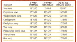
Most suppliers offer new hydraulic and lubricating oils that are certified to a specific ISO cleanliness code. The most widely used method or standard for representing fluid cleanliness is the ISO Solid Contamination Level Code (ISO 4406). One must also make sure the fluid meets Cleanliness Codes per ANSI/(NFPA/JIC) T2.24.1-1991 (see Table 3). Filtering oil before using it is the most cost-effective way to ensure that only clean fluid enters the reservoir.
Environmental contamination comes from the conditions that surround the component or hydraulic system. Airborne contaminants are most likely particles measuring less than 30 µm in diameter. Moisture can enter the system as free water or as condensate from humid air. This type of contamination can enter through reservoir ports and tops that are left open or components exposed during maintenance. In addition, dirt can bypass faulty rod seals. The most effective way to exclude this contaminant type is to make sure system reservoirs are completely sealed, that rod seals are effective, and that some type of filtration system is in place. The system must remove the contaminant before it enters the fluid. Breathers, for example, can absorb moisture and filter solid particles.
Self-generated contamination (particles comprised of wear debris) is generated during system operation. These contaminants must be removed while the component or system is in operation. Pump vanes, rod ends and hoses generate small particles that must be filtered out to prevent debris from causing system wear. Removing contaminant particles as they are generated minimizes this normal “wear and tear.”
Target Levels of Cleanliness
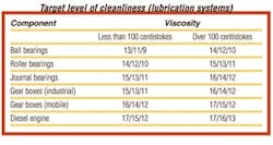
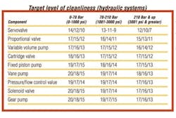
Target Levels of Cleanliness (TLC) is a three-step approach to filtration and contamination. To use this approach, the system designer must begin by setting desired levels of cleanliness, using the ISO Cleanliness Code 4406. Next, the designer must select filters and elements that achieve these levels. The levels should be absolute beta-rated filter elements. Finally, fluid must be monitored on an ongoing basis to ensure that specified target levels are maintained.
The information listed in Tables 1 and 2 can be used to help establish a TLC. Selection is based on information such as critical component clearance, fluid viscosity and operating pressure.
Rating filters
Because of the complexity of filter ratings and nomenclature, filter selection can be the most difficult process of all. Filters are rated by several methods. The three most common are nominal ratings, absolute ratings and Beta ratings.
A nominal rating is an arbitrary micrometer value indicated by the filter manufacturer. However, these ratings lack meaning and reproducibility unless the exact test method is accurately defined. Nominal ratings have generally fallen out of favor.
An absolute rating is a diameter measure of the largest hard spherical particle that will pass through a filter under specified conditions. This indicates the largest pore size in the filter element. It does not indicate the largest particle that will pass through the element, since particles of greater length (than diameter) may pass through.
A Beta rating is derived from the Multi-pass Method for Evaluating Filtration Performance of a Fine Filter Element (ISO 4572). During testing, automatic counters measure the upstream particle size and quantity per unit volume-of-fluid and the particle size and quantity downstream of the filter.
Particle counts greater than or equal to a given size upstream are divided by the particle counts greater than or equal to the same size downstream. This produces a Beta ratio, denoted by the Greek letter Beta, ß. The subscript on the letter denotes the micron size that was tested. For example, a Beta ratio of particles greater than or equal to 3 µm in size, with 50,000 upstream particle counts and 250 downstream particle counts, equals ß3 = 50,000/250 = 200. This filter would have a rating described as “beta sub 3 equals 200.”
The resulting Beta number also can be used to determine the filter element efficiency with the following formula: (1 - 1/ ß) x 100 = percent efficiency. (Using the same example from above, (1-1/200) x 100 = 99.5% efficient.)
The multi-pass test should not be used to correlate how a filter will react under actual working conditions. However, the test can be used to compare the relative filter element life or dirt-holding capacity of different elements, provided they were tested under the same conditions.
Other filter selection factors
The Beta rating of a filter element is important. However, other factors must be considered when selecting a filter. These factors include pressure drop, dirt capacity, system-operating pressure, system-operating temperature and filter location.
- Pressure drop, or differential, is the pressure difference between any two points of a system or component. This is commonly known as the difference between system pressure upstream and downstream of a filter.
- Dirt capacity is the weight of a specified artificial contaminant, which must be added to the fluid to produce a given differential pressure across a filter at specified conditions.
- System operating pressure is the operating pressure range the filter will “see,” which overcomes the total resistance in a system. It includes all losses, as well as useful work.
- System operating temperature is the expected temperature range of fluid expressed in degrees Celsius or Fahrenheit.
- Filter location, or placement of filters within a hydraulic system, can significantly reduce wear and tear. A complete understanding of filtration and hydraulic systems helps in the strategic placement of filters.
Typically, pressure filters are used to provide protection for critical components in the hydraulic circuit, such as servo-valves and direction-control valves. Filter breathers are used on reservoirs to provide filtration of the make-up air required, as the reservoir fluid volume decreases. Return-line filters remove system-generated contamination before returning fluid to the reservoir. A kidney loop filter or filter cart can be used to clean reservoir fluid on an ongoing basis, using the principle of constant dilution.
Monitoring fluids—an overview
To properly monitor system fluids, a plant manager should establish an ongoing maintenance program of oil-analysis testing. By sampling fluid periodically, potential problems can be identified and resolved before they occur; also, specified TLCs can be tracked. In addition, periodic oil analysis is one of the least expensive preventive measures a systems operator can perform.
Understanding the principles of contamination and filtration is as important as the type of component or system that is built or purchased. With a proper understanding of these principles, one can achieve successful system operation. The only requirement: establish a TLC for a specific system, then implement a plan for specifying and using the appropriate filters to achieve that TLC.
Companies that invest in filtration to protect their hydraulic systems ensure protection against premature failure. As the old saying goes, “An ounce of prevention is worth a pound of cure.”


