Compressed air systems hold one of the keys to greater productivity, efficiency and profitability. This is the fifth in a series of articles that introduces some key points of Compressed Air Challenge training.
The greatest expense associated with compressed air is the cost of energy. Compressors operate most efficiently when fully loaded. However, most compressed air systems allow compressors to operate partially loaded.
Compressor capacity control systems regulate air output to match system demand and are one of the most important factors in determining overall system efficiency. To select the most energy-efficient capacity control system, you need to determine the compressor type and the plant’s load cycle.
Start/stop
The most basic form of compressor capacity control is start/stop. It requires compressing air and storing it in an air receiver. When pressure reaches an upper pre-set limit (cut-out), the air compressor turns off and no further air is compressed. The stored air supplies demand.
When pressure drops to a predetermined low setting (cut-in), the compressor starts and the cycle is repeated. The cut-out pressure is typically set 25% above the cut-in pressure. This can be an efficient way to control a compressor, because power is used only while air is being compressed. However, using compressed air at a pressure above the required minimum increases power consumption, thereby partially offsetting any gains. Therefore, many systems will, or should, use a pressure regulator to reduce line pressures to the required minimum. Note that every 2 psi increase in discharge pressure, requires an additional one percent in energy.
Start/stop controls are found on reciprocating compressors ranging from less than one hp to 30 hp. System storage capacity must be considered to provide adequate time between motor starts. Started too frequently, an electric motor can fail prematurely.
Constant speed or load/unload
With constant speed, or load/unload, control, system pressure is set at a high point (cut-out) and a low point (cut-in). However, rather than turning off when system pressure reaches the cut-out point (typically 10 percent above the cut-in setting), the compressor motor continues to run while the compressor operates in an “unloaded” mode. When unloaded, compression is interrupted and the compressor’s internal pressure drops.
Typically, constant speed controls are found on reciprocating and rotary screw compressors, and on some centrifugal compressors. Unloaded input power requirements on reciprocating compressors is 8 to 12% of full-load requirements. On rotary screw units, the unloaded requirement is approximately 15 to 25% of full load power. Constant speed or load/unload controls are used in applications where loads are continuous and a start/stop control would cause premature motor failure.
As with start/stop control, over-pressurization is required to maintain minimum plant operating pressure. When running in the unloaded mode, power is still consumed, but the compressor is not delivering any useful work.
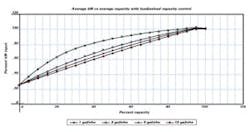
In the load/unload mode, adequate storage is critical for part-load efficiency. Figure 1 illustrates the effect of receiver size on a lubricated rotary screw compressor with load/unload controls .
Dual control
Figure 1.
Dual control allows for manual selection of either start/stop or constant speed control. A typical application would have the compressor operating at a constant speed during production when demand for compressed air is continuous and in the start-stop mode during low demand, non-production periods. Dual control is found on reciprocating compressors and smaller rotary screw units.
Auto-dual control
Auto-dual control automatically selects either constant speed or start/stop control. With autodual control, a reciprocating compressor runs in a constant speed mode. When it unloads, a timing relay is activated. If system pressure doesn’t fall below the cut-in set point within a specified time period, the compressor shuts off. When system pressure eventually falls to the cut-in set point, the compressor restarts and the control process resumes. On a rotary screw compressor with load/unload control, the control process is identical to that for a reciprocating unit. When inlet modulation control is used, the rotary compressor will typically modulate (throttle back) to approximately 40% of full capacity before completely unloading (blowing down). At this point, the timing relay is activated, and assuming system pressure does not fall below the cut-in point within the specified period of time, the compressor will turn off. Overall rotary screw part-load efficiency will be directly affected by system storage capacity when operating in the load/unload mode.
Modulating control
Modulating (inlet throttling) control is found on rotary screw and centrifugal compressors. Modulation allows for stepless output control to meet varying demand. At less than full capacity, the inlet valve throttles back, thereby matching system demand by restricting airflow into the compressor. Because the inlet valve remains wide open (fully loaded) up to the modulation set point, the minimum allowable system pressure and the control set point can be the same.
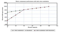
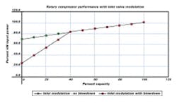
Rotary screw. On a rotary screw compressor, modulation is an inefficient way to control capacity, because it affects the inlet pressure of air being compressed. Throttling the inlet valve creates a vacuum at the rotor’s inlet. This reduces the absolute pressure at the start of the compression cycle, thereby increasing the overall compression ratio. Brake hp is dependent on the volume of air compressed and the compression ratio.
As compression ratios increase, so does bhp. For example, running at 100% capacity, air pressure at the rotor inlet is 0 psig, the same as ambient (assume 14.7 psia). With a 100 psig discharge pressure, the overall compression ratio is 7.8:1. When system demand decreases, the inlet valve throttles back, restricting flow. This results in a lower absolute pressure at the rotor inlet.
Figure 2.
At 65% flow, hp requirements are reduced. However, because inlet pressure at the rotors is reduced to approximately 9.5 psia, more work is required to raise inlet pressure to its final discharge pressure of 100 psig (114.7 psia). As a result, the overall compression ratio is now 12:1. Although less air is being compressed, which reduces the power required, the higher pressure ratio increases input power. As a result, a modulating inlet controlled compressor operating at only 65% of full-flow capacity still requires 91% of full-load power (Figure 2).
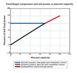
Centrifugal compressors. When applied to centrifugal compressors, inlet modulation offers efficient part-load control, especially if inlet guide vanes are used to direct air in the same direction as the impeller rotation. Required power and output flow are reduced almost proportionately.
On a centrifugal compressor, however, inlet modulation is limited by the percent that inlet flow can be reduced before it goes into surge (flow reversal). This is typically 70 to 80% of full-flow capacity. Below that, modulating a blow-off valve vents excess flow capacity to the atmosphere. Known as a “constant pressure” control, the compressor load remains constant and no further reduction in power is realized. Some centrifugals can operate in load/unload mode below the surge point. Typically, the unloaded hp is 20% of full-load power. Running in the load/unload mode requires adequate storage to maximize part-load efficiency (See Figure 3).
Figure 3.
Variable displacement control
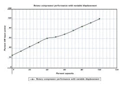
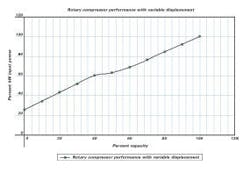
Variable displacement control (VDC) — a lso known as a turn valve, poppet valve or spiral valve — is found on rotary screw compressors at 50 hp or above. Similar to modulation, VDC automatically regulates compressor output to match system demand. Unlike modulating control, however, VDC reduces output by varying compressor displacement, which allows the inlet valve to remain wide open. This is accomplished by opening windows and ports in the cylinder wall that runs along the length of the rotor to return the unneeded air to the inlet rotor before compression begins.
Because inlet air is not restricted, pressure at the rotor inlet is always at the atmospheric level. Therefore, the compression ratio remains unchanged even during part-load operation. As we know, bhp is dependent on the volume of air compressed and the compression ratio. By maintaining a constant compression ratio and decreasing the volume to be compressed, power requirements are reduced almost proportionally.
For example, at 65% flow, a variable displacement rotary screw compressor requires approximately 75% of full-load power. In many cases, VDC regulates output from full capacity down to 40% of flow. Below that, the compressor operates in load/unload mode or by modulating the inlet valve as previously described (Figure 4).
Figure 4.
Variable speed drive control
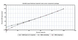
A variable speed drive controls compressor speed to match output with demand. As system pressure rises above the set point, the drive reduces compressor speed by changing the frequency supplied to the motor. The efficiency loss across the drive is typically between two to four percent.
Compressor displacement is directly proportional to speed. By controlling displacement via speed and not restricting inlet flow, the compression ratio remains constant. This results in relatively good part-load efficiencies.
Rotary screw air-end compressor efficiency is a function of rotor tip speed. Operating the rotor at any tip speed other than the designed optimum speed increases specific power (kW/100 cfm) and reduces overall compressor efficiency. Adjusting compressor rpm and, therefore, rotor tip speed to match system demand results in less than optimum operating efficiency at most load settings.
When running fully loaded, most VSD factory packages operate the air-end above optimum rotor tip speeds. This allows the air-end to operate at a more efficient rotor tip speed at part load; however, less than maximum air-end efficiency is realized at full load.
Figure 5.
Typically, VSD-controlled rotary screw compressors improve efficiency at reduced flows. The best energy savings come from applications in which most system demand is in the low- to mid-capacity range. VSD typically can regulate compressor output down to 40% of full load — and in some cases, as low as 20%. When operating below the VSD range, capacity is controlled in either the load/unload or start/stop modes (Figure 5).
Multiple compressor systems
When operating a facility with multiple compressors, an efficient overall control scheme should focus on three items:
- Shut off unneeded compressors.
- Delay bringing additional compressors on line until absolutely needed.
- Make sure compressors are operating fully loaded or in the most energy-efficient partial-load control mode possible.
Ideally, in a multiple compressor system, only one unit should operate at less than full load. This unit is referred to as the “trim” compressor. Centrifugals, or rotary screw compressors with modulation controls, make good base-load units. Reciprocating compressors and rotary screw packages with variable displacement or VSD controls are good choices to operate as trim units. Rotary screw compressors with on-line/off-line controls also run efficiently as trim units, provided adequate system storage is available. When determining the required ratio of system volume to system capacity, only the trim compressor’s capacity need be considered.
For example, let’s take a plant compressed air system using three 1,000-cfm rotary screw compressors. Average system demand is 2,400 cfm, with some 2,800 cfm peaks. Assume the full-load hp requirement is 220 bhp per compressor. With all units running in a modulating control mode, average power will be approximately 627 bhp or 95% of full-load power, while delivering only 80% of full-load capacity (Figure 2). By running two units fully loaded (2,000 cfm) and the third one as the trim compressor (40% load, 400 cfm), average power requirements still remain at approximately 616 bhp or 93% of full-load power (Figure 2). By running the trim compressor in the load/unload mode and installing 5,000 gallons of storage capacity (5 gal/cfm of trim compressor capacity), the new average power requirement drops to approximately 576 bhp or 87%of full-load power (Figure 1).
Figure 4
Using variable displacement control on the trim compressor, average power requirements will be approximately 581 bhp or 88% of full load (Figure 4). With variable displacement control, the 5,000 gallons of storage are not necessary to maintain part-load efficiency. Therefore, storage system size can be limited to meet intermittent demand surges or other plant requirements.
If you understand how your compressor’s capacity controls work and affect part-load power, you can implement an energy-efficient control strategy, thereby lowering your plant’s overall energy costs.
Collaborative effort
The Compressed Air Challenge (CAC), a non-profit corporation, began in 1997 as a collaboration of public, non-profit and private organizations dedicated to increasing the understanding and improving the efficiency of compressed air systems within the U.S. industry.
The purpose of the CAC is to provide a solutions-neutral environment for educating both suppliers and users of industrial compressed air systems on the benefits of taking a “systems approach.”
The CAC has developed two levels of training for plant engineers: “Fundamentals of Compressed Air Systems” and “Advanced Management of Compressed Air Systems.” Other educational products include publications, such as the Sourcebook. Other materials are under development. For more information, call 800-862-2085 or visit http://www.knowpressure.org.
