Manufacturers must produce an exploding array of products faster than ever while reducing costs and increasing operational efficiencies to previously unreachable levels. To meet these demands, companies are increasing the amount of automation within their plants. While this additional electronic equipment is helping boost production, it is also contributing to an increase in harmonic distortion problems. Variable frequency drives often comprise a large portion of this new equipment, so drive users are taking a close look at harmonics issues and evaluating potential mitigation strategies.
Harmonics defined
Harmonics are deviations from the base AC line voltage and current waveforms. Most electrical circuits in North America operate at 60-Hz frequency. A harmonic frequency is a multiple of this base frequency. In a 60-Hz system, for example, the second harmonic would be 120 Hz, the third would be 180 Hz, and so on. Any frequency other than the base creates distortion. The more harmonics present, the more distortion in the electrical waveform.
That's the technical definition. In its most basic description, however, harmonic distortion is simply electrical noise. Non-linear loads, which are drawing power throughout a facility, create this noise. If the plant’s non-linear load is significantly larger than the linear load, there is a potential for harmonic distortion problems.
Other sources
While drives certainly contribute to harmonic problems, they aren't the only causes. In fact, any equipment that converts alternating current (AC) to direct current (DC) can create harmonic distortion. This includes many of the systems used on the plant floor, such as welders, arc furnaces, process controllers, lighting systems, DC power supplies and uninterruptible power supplies.
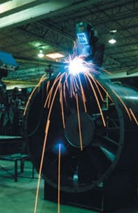
Many industrial operations, such as electric welding, can generate harmonics.
Harmonics problems usually aren't catastrophic, but they can cause equipment overheating, erratic system operation, nuisance tripping and noise transfer to other loads. This can lead to equipment damage and production downtime. In extreme cases, utilities can impose penalties on power users or even disconnect a facility from the power grid until harmonic problems have been resolved.
Clearing the confusion
Although awareness and concern about harmonics has grown considerably in recent years, it’s often misunderstood, inaccurately diagnosed and ineffectively mitigated. Therefore, before rushing out and purchasing additional hardware to solve a perceived harmonic problem, it's important to first address a few basic questions.
- Is there actually a harmonic problem within the system?
- If so, exactly what is causing the problem?
- Based on the application and the identified cause, which of the many solutions is the best one?
As the number of drives used in automation systems grows, so too does the misconception that they are always the single largest cause of harmonic problems. While drives comprise a sizable portion of non-linear loads, they are only one element in the harmonic equation. That's why, before making any final conclusions, it's important to analyze every electrical load that has the potential to cause problems. The bottom line is that not all installations have a problem, and not all problems are drive-related. In fact, there are hundreds of thousands of drives operating in the field without necessitating harmonic mitigation.
Measuring harmonics
Because utility power feeds supply multiple customers, a harmonic problem in one location can severely distort the power supply and cause problems for others. IEEE519-1992 is the North American harmonics standard for power utilities, and is often imposed on large consumers and medium voltage systems. Total harmonic distortion limits are recommended based upon the type of installation. This specification also has become common in low-voltage systems.
The ability to measure harmonics is important for isolating the cause and recommending potential remedies. In many cases, utilities use special meters that are connected to the power lines feeding a plant to measure the total harmonic distortion. Other instruments, such as high-speed spectrum analyzers, determine the waveforms and help isolate the root of a harmonic problem. Once users have identified the problem, they can implement a number of approaches to reduce or eliminate the effects of these unwanted frequencies (harmonics).
Eliminating bad vibes
As the occurrence of harmonics becomes more prevalent, drive manufacturers are offering more advanced solutions to address the problem. Some are small and inexpensive, while others require additional hardware and are more technically complex. While many of these solutions exceed IEEE 519-1992 requirements and may provide added benefits, such as improved power factor, it's important to evaluate the requirements of the application and select the solution that offers the best fit.
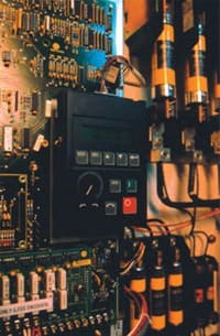
A typical plant installation may include drives alongside other electrical elements
Drives using pulse width modulation technology with the least distortion today are 12- and 18-pulse AC variable frequency drives. They produce little transient noise and can offer a total harmonic distortion of less than three percent. And with a 0.95 power factor, or better, these drives eliminate the need for power factor correction capacitors and tuned inductors.
Power factor is the percentage of usable real power (in Watts) to the utility-supplied apparent power (in volt-amps). The closer a product can come to achieving a 1.0 power factor, the better. In most cases, a power factor of 0.85 or higher is considered sufficient by the utility.
What's important to understand is that there is more than one way to approach the harmonics problem. And the most expensive method may not always be the best choice. It's not uncommon for power users to oversize the solution to eliminate a perceived harmonics problem. But this oversizing correlates directly to cost increases that could be avoided by better assessing harmonic mitigation options. Table 1 provides a cost-performance-size comparison of various drive harmonic mitigation solutions.
Making an informed decision
When addressing harmonics issues, users should keep the following in mind. First, not all installations have a problem. Second, if there is a problem, the solution doesn't always have to involve adding more hardware to the system. Third, while plants need to take precautions, keep in mind that each application is different.
The bottom line is to make an informed decision. Measure the load, determine how many potential harmonic sources exist, assess future conditions and carefully consider the various options available. Then, based on cost and benefits provided, select the solution that fits the application.
| Drive harmonic mitigation technique |
Comments |
| 6-pulse AC drive without a DC link choke | The simplest design of the AC drives. Doesn’t provide any harmonic mitigation capability. |
| 6-pulse AC drive with a DC link choke | The choke provides reduction of low frequency harmonics produced by the drive. |
| Input line reactor | Reduces surges or spikes on the line. Provides enough harmonic mitigation on distribution systems that have a very small percentage of non-linear loading. |
| Tuned and non-tuned harmonic filters | Cost and performance effective but can cause power system resonance in some installations, especially if there are any future system impedance changes. |
| 12-pulse converter with auto transformer | Reasonable performance and cost effective, but does not guarantee meeting IEE519-1992 without analysis. Less component count and design complexity compared to an 18 pulse. An auto transformer will have a lower cost and smaller physical size (easier to mount in the enclosure line-up) than an isolation transformer. |
| 12-pulse converter with isolation transformer | Reasonable performance and cost effective, but does not guarantee meeting IEE519-1992 without analysis. Less component count and design complexity compared to an 18 pulse. An isolation transformer supplies slightly less THD than an auto transformer and non-proprietary designs are more readily available. |
| 18-pulse converter with auto transformer | Can guarantee meeting IEEE519-1992 limits at the drive input terminals without analysis provided the input power phases are balanced within 1 percent. An auto transformer will have a lower cost and smaller physical size (easier to mount in the enclosure lineup) than an isolation transformer. |
| 18-pulse converter with isolation transformer | Can guarantee meeting IEEE519-1992 limits at the drive input terminals without analysis provided the input power phases are balanced within 2 percent. An isolation transformer supplies less THD than an auto transformer and non-proprietary designs are more readily available. |
| Regenerative active front end | Has the added feature of regenerative braking back to the line. Generally only cost effective on large common bus systems with many drives and/or high horsepower ratings. |
| Active power filter | Most technologically advanced solution but generally only cost effective on large common bus systems. |
Photos courtesy Rockwell Automation
Bruce Hachey is engineering manager for the Allen-Bradley Custom & Configured Drives Business, Rockwell Automation, a product group that specializes in adding additional value to standard drive products. George Zenke is a product manager with Rockwell Automation. For more information, visit http://www.rockwellautomation.com.


