Often, the five-step (variable-displacement) controller on a new central compressed air management system running large capacity, lubricant-cooled rotary screw compressors is modified to a two-step controller. This may lead to short cycling and the multiple units all operating at part load.
When reciprocating air compressors were king, people quickly realized that as compressor capacity exceeded 1,000 cfm to 1,500 cfm, it became harder to use a two-step unloading system (for example, full flow at 90 psig to 99 psig and no flow at 100 psig). High capacity and two–step control led to system "overdrive" at part-load conditions often causing operation at excessive system pressure and extreme short cycling, which is hard on the equipment.
Then came three- and five-step unloading systems. The five-step system, the most effective, unloaded the compressor stepwise from 100% flow to 75% to 50% to 25% to 0% flow, usually through a series of clearance valves. At no flow, the unit idled at the lowest energy draw or shut off completely. These controls produced a quicker response to system demand, thus minimizing pressure surges and drops as the system maneuvered to match supply to demand.
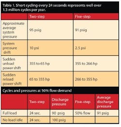
For example, a two-step control on a 1,600-cfm compressor set to load at 90 psig and unload at 100 psig with 3,500 gallons of effective storage will pump up from 90 psig to 100 psig in 129 seconds at a demand of 1,450 cfm. At 100 psig, the inlet valve will shut, and no air goes to the system. In 12 seconds, the pressure will fall to 90 psig and the compressor will pump up again. Cycling every 24 seconds (which the two-step control does at 50% load) represents well more than 1,300,000 cycles per year, which is tough on valves, bearings and other components.
Under the same conditions with a five-step control, the compressor operates with the following cycle: in three seconds, the first clearance pocket opens and the flow falls to 1,200 cfm, 88% flow. The pressure falls to 90 psig in a little more than four seconds, the clearance pocket closes and the unit runs at 100% flow (1,600 cfm). When the system pressure falls back to 90 psig and the poppet or clearance valve closes again putting the unit at full load. The results are shown in Table 1. Generally speaking, the primary benefits of a five-step central system were a 4% to 8% energy savings and a significant reduction in cycles and system pressure rise during operation. Larger two-stage, oil-free rotary screw compressors, which are either two-step or use a variable-speed drive, would be similarly affected. Reciprocating units and oil-free rotary screw units exhibit a negligible negative effect on input energy use during short cycling.
Effective storage affects cycle time. Doubling the storage doubles the length of each cycle. Whenever possible, put a large two-step unit on base load if that configuration fits the demand cycle and the available other equipment.
Lubricant-cooled rotary screw units
The cycle data still applies, but the energy picture is much more dramatic. A lubricated rotary screw compressor must “bleed down” the pressure in the oil sump/tank before input energy reaches its lowest level at full idle. At the unload signal, the inlet valve shuts and the pressure trapped in the oil sump/tank between the closed minimum pressure valve and the closed inlet valve is 100 psig. The immediate responses we measure in the field under these conditions range from no perceivable drop in input kW to about a 15% or 20% drop.
The tank then begins a controlled bleed down to a predetermined minimum pressure of 7 psig to 35 psig, depending on the brand, model and age of the units involved. The bleed down can’t be too fast, which froths the oil, possibly saturates the separator’s element and potentially causes excessive oil carryover. Units manufactured before 2000 might have significantly larger tanks and require a longer bleed down time. We have timed some 300/350-hp units with bleed down times of more than three minutes and 150-hp units needing more than 90 seconds. Newer units with smaller tanks require much less time. Some 150-hp units can bleed down to around 7 psig in 30 seconds. This obviously reduces operating costs at idle.
The potential energy savings with a two-step controller can be virtually zero if the lubricant-colled rotary screw compressor doesn’t stay at full idle (no flow) long enough to achieve full blowdown. When we talk of units in the 1,200 cfm to 3,000 cfm range, we talk of large separators, large oil sump/tanks, longer bleed downs and potentially shorter cycles. Absent careful installation and a sophisticated control system, everything is going the wrong way to capture real savings with two-step controls. A few software programs for central air management systems can keep multiple large two-step units at full load and one as a trim unit at part load (all others off) 85% to 90% of the time.
But a lot of the software out there works well on smaller units, but not on larger units. The lubricant-cooled rotary screw compressor’s answer to the five-step control is the idea of "variable displacement." This scheme uses either poppet valves or a high-lead spiral valve to clear and close multiple openings in the cylinder.
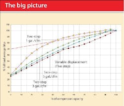
Moving the seal in the cylinder towards the discharge effectively bypasses some of the trapped air that was to be compressed. Reducing the flow in response to sensed demand without reducing the inlet pressure below the inlet valve helps the overall part-load efficiency. Except for special application units, almost all of these use four openings that open and close. Each opening is designed to reduce the flow by about 12.5% and operate at an approximate two psig change in pressure as standard. These operate sequentially at every two psig change down to about 50% demand. Below that, the control shifts to modulation or two-step at the lower flow, depending on the situation and design. From 100% load to 60% or 70% load, these capacity controls operate at favorable part-load efficiencies (Figure 1).
Click to enlarge Fig. 1
A well-applied central air management system uses the “five-step characteristics” of the lubricated rotary screw compressor variable-displacement control. It knows the control’s load position and manages the system accordingly. Too often, people with limited software capability convert large variable-displacement-controlled compressors to two-step, and the results are short cycling, high system pressure fluctuation, and multiple units running at varying part loads as the system dynamics outrun the control response.
Some examples
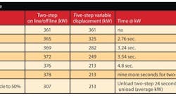
The following charts depict the basic action and input kW for a 1,600-cfm unit in two-step and five-step (variable-displacement) control. The five-step has consistently lower kW at lower loads and almost seamless transfer. The two-step unit runs full load over the entire pressure band (10 psig) before it unloads and goes to no flow.
Table 2 is based on a 1,600 cfm 450-hp single-stage rotary screw compressor with a motor that is 93% efficient (361 kW input). The compressor has an operating band of 90 psig to 100 psig and a two-minute blowdown. The full blowdown idle shaft input is 90 hp (75 kW), the effective storage is 3,500 gal and there is a 10-psi loss between compressor and receiver.
Click to enlarge Table 2
With a 12 sec. off time and two minutes required to blow down, the power input will reach approximately 298 kW before the two-step unit reloads. This gives an average kW for the unload cycle of 329.5 kW. Running 12-sec. on/12 sec. off is a serious short cycle problem that burns power and damages bearings, coolers, switches, etc. The five-step control, on the other hand, runs at a continuous 213 kW at 50% load.
At demands below 50%, the five-step unit is in modulation with blowdown (800 cfm) and a 48-sec. idle.
The overall comparison between it and the two-step control varies greatly, depending on conditions. A duty cycle that includes much time below 50% represents a serious misapplication to be corrected.
Because no trim unit can run at full load all the time, let’s see what really happens to kW and cycle time with a two-step and five-step control system, both with a control band from 90 psig to 100 psig.
At a continuous 88% load (Table 3a and 3b), the two-step unit runs 100.6 sec. (1.68 min) to reach 100 psig before unloading. The average power consumption for 100.6 seconds is (379.2 + 364.5)/2 = 371.7 kW. The two-step control idle time will be 12 sec. and blowdown will use about 329.5 kW (compared to full idle of 75 kW). The total time at 371 kW average is 100.6 seconds and the total time at 270 kW is 12 sec. Under these static conditions, the five-step control is 11% more power efficient. There are no cycles compared to one full cycle every 112.6 sec. The pressure is held at 92 psig continuously while the two-step unit goes from 90 psig to 100 psig and back.
Click to enlarge Table 3
At a continuous 75% load (Table 4a and 4b), the two-step unit runs 48 sec. (0.8 min) to reach 100 psig and unloads while using an average kW of (379.2 + 364.5)/2 = 371.7 kW. The two-step control idle time will be 12 sec. and the blowdown will use about 329.5 kW (compared to full idle of 75 kW). The total time at 371 kW average is 48 sec. and the total time at 329.5 kW is 12 sec. Under these static conditions, the five-step control is 22% more power efficient. There are no cycles compared to one full cycle every 60 seconds. The pressure is held at a steady 92 psig while the two-step unit still oscillates between 90 psig and 100 psig.
Cllick to enlarge Table 4
To read 5 always beats 2 (Part 2), click here.
Hank van Ormer is owner of AirPower USA, Pickerington, Ohio. Contact him at [email protected] and (740) 862-4112.


