A truism characteristic of the modern business model is that more work is expected to be done by fewer people. Overseas competitors, regulation of many aspects of business and unrealistic investor expectations concerning short-term returns have conspired to produce this financial squeeze.
Opportunities for effective on-the-job training have vanished as the pressure to treat every job as a crisis has become the norm. As a result, managers sometimes feel justified taking shortcuts that would have been inconceivable even a generation ago.
This means that quite often small details get overlooked. Most of the time, inattention to the small stuff wont cause a problem you can usually get away with driving to the store without a seatbelt. But every now and then, one of these problems rears its ugly head and bites. Consider the saga of how a small problem chomped down and wounded several unwary maintenance professionals.
A small pin, installed incorrectly, cost a large manufacturer millions in lost opportunity. It forced production into a significantly reduced schedule for more than one month and resulted in an extremely expensive repair. Total losses exceeded $2 million. Following just a few simple steps and giving plant personnel proper training and supervision would have avoided all of this misery.
Making the fix
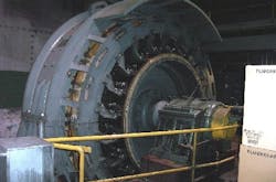
The main character in this story is a large, multi-pole DC motor rated for several thousand horsepower at only 40 rpm (Figure 1). Motors of this type used to be common in the metal and paper industries, to name a few, but their numbers have dropped as these industries have closed operations and moved production offshore. Because there are fewer of them in the market, there are fewer individuals that know how to repair them. Motors of this type have been known to provide more than 80 years of service when properly maintained.
Figure 1. This 40-rpm, multi-pole DC motor was brought low by a bad diagnosis.
In September 2002, a routine insulation test on the motors armature circuit showed that it was grounded. Subsequent isolation and inspection indicated that the source of the trouble was in the armature itself. That component weighs 89 tons and is completely surrounded by a field frame having less than 3/8 in. of radial clearance. Seeing no visible signs of trouble and experiencing no operating failures, the plant decided to clean the armature with dry ice to improve the insulation resistance before resuming normal operations.
Dry ice is a popular medium for abrasive cleaning, especially in electrical equipment. In the hands of a qualified operator, it does a respectable job of removing dirt from exposed surfaces and the abrasive evaporates shortly after use, leaving only dislodged dirt to be blown out the housing.
Unfortunately, the wands that direct the dry ice stream are usually one foot or more in length. Combine this geometry with a large-bore hose and youve imposed significant limitations on the surfaces that can be accessed and cleaned.
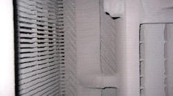
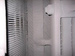
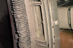
Figure 2 shows the back of the commutator side support ring in a large armature. The risers are on the left and the coils can be seen running diagonally at the center. To give some feel for the inaccessibility of this area, the photograph was obtained by holding the camera down a three-foot deep hole and shooting blindly. The area is difficult to clean in the controlled environment of a repair shop with a steam cleaner. In the field with other obstructions around it, this becomes almost impossible.
Figure 2. The back of the commutator side support ring with the risers on the left and the coils running diagonally.
The critical location for dirt buildup is between the support ring and the armature laminations. These are the places where dirt builds up and most insulation failures occur in this type of motor. Imagine trying to steer a one foot wand with a 1.5-in. hose attached to it while wearing protective gear and youll have some appreciation for the difficulty in obtaining a good cleaning job.
In addition, many times the cost of dry-ice cleaning is kept down by not disassembling the frame around the motor or removing the brush rigging, cooling equipment or other obstructions. The cleaning company is merely told to do the best they can. Unfortunately, the air gap (the clearance between the armature and the field frame) is usually less than 3/8 in. and brush rigging is often directly in front of that gap. With these restrictions, even the best operator is forced to miss significant portions of the windings.
As youd expect, dry ice cleaning produced no appreciable improvement in insulation resistance, but the motor was returned to service until an outage could be scheduled to disassemble and inspect the armature.
Going to plan B
During the next maintenance turn, mill personnel pulled the top frame half to better inspect the in-service armature. This revealed a hole in the armature where a coil had grounded (Figure 3). The armature was replaced. While the armature was out, the mill discovered several faulty field coils. This meant that the frame had to be pulled and sent to an outside repair facility to rewind the coils. It was late September after more than two weeks of downtime and beyond the planned outage before the motor was reassembled with the new coils and armature and returned to service.
Figure 3. This hole in the armature is where a coil had grounded.
After several sporadic circuit trips in August 2004, an electrician noticed that the armature moved when the fields were energized. Because the armature is theoretically centered in a uniform magnetic field, it shouldnt move when the fields are energized. Inspection showed that the air gap -- the space between the armature and the field poles -- varied by approximately 0.210 in. to 0.335 in. from one side to the other. Most manufacturers standards recommend a maximum variation of 5% on new installations and 10% for field verification on large DC machinery. The motor in question was obviously outside of that tolerance.
The magnetic field on the side with the small air gap is much stronger than it is on the opposite side. This inequality produces a net sideways force and pulls the armature off-center, which makes the problem even more pronounced.
Think of trying to hold a steel rod exactly centered between the two poles of a horseshoe magnet. As soon as there is the slightest bit of motion to one side, magnetic attraction becomes so great that its almost impossible to keep the rod from touching the magnet. In the case of a motor armature, the only thing restraining the armature is the shaft bearings.
The second effect of this eccentricity is to vary the counter electro-magnetic force (CEMF) that opposes the current in some portions of the armature. This produces circulating currents and can cause poor commutation, both of which are detrimental to machine operation and health.
The mill reset the air gap to the 10% tolerance. Because the armature position is determined by the location of the driven machinery, this adjustment is performed by moving the frame. The dowel pins were pulled and the base bolts loosened in preparation for the move.
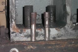
Thats when the maintenance crew noticed rust lines on the dowel pins (Figure 4). The oxide appeared only on the exposed portion of the pin. The tight fit in the holes protected the rest of the dowel from corrosion.
Figure 4. The root cause of the problem was a dowel pin that had never been seated, allowing the frame to move.
The rust line on the side of the dowel pin with the reduced air gap plainly showed that it had never been seated into the base. It also showed where someone tried to grind the dowel tip in an attempt to seat it, apparently without success. This was the root cause of the problem. One dowel pin had never been seated and the frame had moved, probably under the type of transient load that is normal for this machine.
To reset the air gap, the outside contractor slid long feeler gages between the armature and the field poles on both sides of the machine. The banding on one end of the armature was scraped and cut during this process (Figure 5). When the mill complained, the contractor agreed to patch the bands with an adhesive to minimize the frayed ends. Unfortunately, gluing down the ends didnt restore the band strength. After the repairs were completed, the mill returned the motor to service.
Figure 5. The contractor sliding long feeler gages between the armature and the field poles scraped and cut the banding on one end of the armature.
The motor failed again in September 2005. Inspection revealed that the armature installed in 2002 had gone to ground near the pinion end, a common location for a failure with a motor of this style because the coil can be moved under magnetic and centrifugal forces where it exits the laminations. Although this movement is small, its adequate to tear insulating paper and crack varnish, especially after thousands of repetitions in the course of operation.
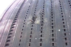
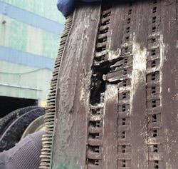
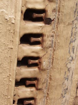
This explains why proper banding is critical -- it restricts this motion. Inspection of the failed area revealed loose banding and a distinctive chevron crack in the insulating varnish at the end of every coil slot (Figure 6 and Figure 7). Evidently the banding repair had failed enough for the coil end turns to move. In a higher-speed machine, centrifugal force probably wouldve thrown the coils completely out and stopped the machine. In this case, the looseness allowed the insulation to crack until one of the 800 or so coils grounded.
Figure 6. Loose banding resulted in this hole in the armature.
Figure 7. Loose banding produced these distinctive chevron cracks at the end of every coil slot.
Onward to plan C
The mill now installed a new armature and rewound additional field coils that had been neglected during the first repair. The motor was returned to service after several more weeks of downtime.
Why is any of this important to motor reliability? Because it shows the cost of poor maintenance and faulty repair practices in terms of future repairs and unplanned downtime. Its clear that somebody knew the dowel pin wasnt engaging properly as evidenced by the grinding marks. Yet the underlying cause wasnt identified and the machine was returned to service with a problem that eventually cost the mill dearly in additional repairs and lost opportunity through reduced operating ability. This is simply an unacceptable mode of business in todays competitive environment.
Douglas K. Smithman, P.E., is owner of EMP Engineering Services. Contact him at [email protected] and (215) 793-9783.
