Capture drive system advantages while retaining reliability
You’ve spent a lot of time and money converting to an electronic drive system. The vendor has promised energy savings and increased production efficiency. You’ve carefully matched the supply, the drive, the motor, power conditioning and the process. The trick now is to capture the advantages of the system by maintaining its efficiency and reliability.
We know from studies by United Airlines and the U.S. Navy that nearly every complex machine fails in a random manner. The bathtub curve doesn’t really apply to a motor drive -- there’s no wear out period. Nor does it make sense to do preventive replacement or overhaul. That leaves you with predictive maintenance (PdM) or condition-based maintenance (CBM).
The basic premise of CBM is to detect a potential failure in its early stages so that we have time to take action to accomplish the remedial action in a planned manner. The idea is to manage the failures instead of letting them manage us.
Let’s design a CBM system for a typical motor-drive system. Instead of picking the technologies we want to use and then trying to apply them to our system, we’ll use a machine-centered healthcare approach.
Machine-centered approach
A machine-centered approach starts with the machine and, through a series of steps, helps you decide what tests to perform. It has six steps:
- List the system functions.
- List the possible failures to meet those functions.
- Decide which failure modes are significant.
- Decide how to get an early warning.
- Select a suite of tests to detect those early warning signs.
- Collect the test results at one decision point.
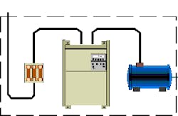
List the system functions: Identifying possible failures requires knowing what the machine is supposed to do -- its primary and secondary functions. For this example, we’ll examine a system from the power supply cables to the motor output shaft (Figure 1).
At first glance, you might say that a motor-drive system’s primary function is to provide power to the shaft. In reality, its primary function is more complex than that. It must provide a minimum torque at a specific RPM. It may be required to accelerate a load from stop to operating speed, control speed ramp-up and ramp-down, and respond to signals from a control system. Other possible functions (Table 1) might be to maintain power factor, minimize source wave form distortion and maintain phase balance.
|
Downstream (load side) |
Upstream (line side) | Power supply |
| Start motor Stop motor Deliver specified torque at specified RPM Specified speed ramp up rate Specified speed ramp down rate Accelerate load from stop to operating speed Adjust torque and speed on demand |
Reduce power usage Maintain power factor below limit maintain total harmonic distortion below preset limit |
Maintain minimum voltage at max load Maintain voltage balance Maintain phase balance |
Don’t try to use this example without referring to your own system. You may have functions that aren’t listed and some of those listed might not be applicable to your system. Use this as a starting point.
List the possible failures to meet those functions: Once you’ve decided what the system’s function is, ask what can happen to prevent it from meeting that function. In the case of the motor-drive system, the answer might be the motor not starting, poor speed control, high total harmonic distortion (THD) reflected back into the power supply, or a number of other possible failures (Table 2).
| Function | Functional failure | Failure mode |
|
Downstream (load side) |
||
| Start motor | Motor won't turn | Winding failure (stator) |
| Insulation failure (stator | ||
| Rotor failure | ||
| Bearing seized | ||
| Loss of Power | ||
| VFD malfunction (start control) | ||
| Deliver specified torque at specified RPM | Motor turns at wrong speed | VFD malfunction (speed control) |
| Load fault | ||
| Specified speed ramp up rate | Motor ramps up at wrong rate | VFD malfunction (ramp up) |
| Winding failure (stator) | ||
| Accelarate load from stop to operating speed | Load won't reach operating speed | VFD malfunction (ramp up) |
| Winding failure (stator | ||
| Load reaches operating speed too slowly | VFD malfunction (ramp up) | |
| Winding failure (stator) | ||
| Bearing seized | ||
|
Upstream (line side) |
||
| Maintain power factor below limit | Power factor outside limits | Power conditioning fault |
| Maintain THD below limit | THD exceeds limits | Power conditioning fault (THD) |
| Distribution problem (THD) | ||
At this point, don’t consider whether the failure is likely or has much impact. You’re just brainstorming for a complete list. Some functions can fail in more than one way. The table lists failures both upstream and downstream of the motor and drive. Some of these may be attributable to the supply transformer, but they still affect the motor-drive system.
Decide which of these failure modes are significant: Armed with a list of possible failures, rank their importance. Limited resources mean we can’t manage them all. Some failures are so unlikely that you won’t think to worry about them; others have such a low consequence that their effect and cost are minor. But both of these might be significant over time.
The significance of a failure is the combination of two factors: frequency and impact. A small failure that occurs often can have the same impact as a large failure that occurs infrequently. For example, a motor bearing might fail once a month (a chronic problem) because the drive belts are too tight. The cost to replace it is $2,000. Over five years, that’s $120,000. But because individual failures aren’t major, bearing failures won’t receive the same visibility as a single failure costing $120,000 that occurs only once in five years (an acute problem). But they both cost the same.
Use your machinery history to determine a failure’s frequency and impact. Search for chronic and acute problems. Try to determine their costs, including labor, parts and downtime. Figure out how often they occur. Multiply cost times frequency and rank by the result.
Now it’s time for a judgment call —- which failures should you worry about? Any failure that presents a safety hazard automatically goes to the top of the list. Often, only a few will have a high rank and you can concentrate on them. Other times, most will have a high rank. This is where your knowledge of the machine and professional judgment come into play.
Decide how we can get an early warning: Identify the symptoms of each failure mode. A motor might draw more current because of misalignment or a overtight seal. Clogged cooling fins or voltage unbalance might cause overheating. Failed power conditioning might increase THD. Make a list of symptoms for each failure.
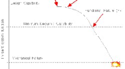
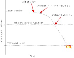
It’s useful to think about the process of failing in terms of a PF Curve (Figure 2). This curve illustrates the relationship between the failure symptom and time. There’s a point where the symptom is sufficiently developed to be detected with confidence. This is called the P point, or potential failure point. The value of the symptom when the process is no longer capable of meeting requirements is called the F point, or functional failure point. Note that the F point is not necessarily the point of mechanical break up.
We want to find a measurable variable that meets several criteria. First, it must be a reliable indicator of machine health and a reliable measure of a symptom. It must be capable of being measured economically. And, it should give sufficient warning so there’s time to react.
Identify the symptoms of failure for each failure mode. Polarization index might point to deteriorating insulation, winding faults by increasing temperature and current draw, or loose connections by increasing temperature. Don’t limit yourself to high-tech test methods -- process variables and visual inspections are too valuable to ignore.
Select a suite of tests to detect those early warning signs: With a list of symptoms, you’re now in the position to select tests that measure or detect each symptom. Try to identify as many independent tests as possible (Table 3). The more information you have, the more confident you’ll be in your judgment call. Have at least two tests for each failure that can confirm each other and avoid false positives (or negatives).
| Function | Functional failure | Sev | Failure mode | Prob | Rank | Failure sources | Symptoms | Measurements |
| Start motor | Motor won't turn | Winding failure (stator) | Conductor failure | Vibration>ips | Vibration monitoring, motor current signature analysis, motor circuit evaluation | |||
| Insulation failure (stator) | Excessive current | Temperature>F | Thermometer Ammeter |
|||||
| Voltage spike | Power quality monitor | |||||||
| Bearing seized | Excessive Temperature | Motor temparature>F | Thermometer, thermography | |||||
| Fatigue | Vibration>ips | Vibration monitoring | ||||||
| Loss of Power | Supply failure, over current device | |||||||
| VFD malfunction (start) | Component failure, program error | |||||||
| Stop motor | Motor won't stop | Contractor failed | See above | |||||
| Deliver specified torque at RPM | Motor turns at wrong speed | VFD malfunction (speed control) | See above | |||||
| Load fault | Overload |
Collect the results of the tests at one decision point: Many plants have some form of condition assessment program in place. But, as a rule, those programs operate in relative isolation. Doing the tests without putting the information together doesn’t represent effective maintenance.
Each machine should have one or two individuals assigned to monitor its health. These employees should be trained to assess the information the tests provide. They don’t have to know how to analyze the data (vibration spectra); they just have to understand the results (information) of that analysis. They should receive the results of the tests and any other pertinent information on a regular basis. Then, they can use that information to manage the machine.
Manage failures instead of having them manage you. Assess machine health based on several independent measures. Perform only those tests and tasks that are cost-effective from the machine’s point of view.
James W. Taylor is director of operations at Machinery Management Solutions, Inc., Clarks Hill, Ind., and is affiliated with the Society for Machinery Failure Prevention. Contact him at [email protected] and (765) 366-4285


