The recent Northeast Blackout should be a wake-up call for the electric utility industry. Fifty million people were without power for as long as thirty hours. Early reports indicated that at least three people died as a direct result of the blackout. Economic losses from the event have been estimated to be well into the billions of dollars. If you have any doubt about the blackout's economic impact, just look at what happened to your gasoline prices.
I hope the blackout didn't affect your plant. But, even if you didn't experience an outage, you may have seen delays in your plant's supply chain. There are lessons to be learned, including how to better prepare a plant for a repeat incident. The blackout was caused by a series of events tied closely to the protective relays on a number of utility systems. Knowledge of protective relaying will help you to understand your plant's protective relaying, and its role in the utility system supplying power to your plant.
Power system stability and protection are complex. However, there's little doubt that a series of events led to the blackout. Lacking proper system protection schemes allowed some disturbance to cause electric generators to "swing" or oscillate, causing large amounts of power to slosh back and forth from one part of the grid to the other. The oscillation was so great that generators started tripping off line. And once a coal-fired or nuclear plant trips off-line, it can take hours, even days, to get it back on-line.
If a plant's electrical system is operating at its limit, it can fall apart, just like the Northeast utility grid. Preventing some small electrical system component from darkening the entire plant requires an understanding of protective relays.
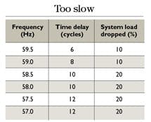
Table 1. Example of under-frequency load shedding.
Note: These setpoints are for illustrative purposes only and may not reflect a particular utility's setpoints.
The devices that could have prevented the blackout were either not installed or, if they were, didn't operate properly. You're likely to hear a detailed explanation of what went wrong, and the U. S. government plans to pass utility reliability legislation.
What you probably won't hear about is the hardware that operated properly and contained the outage. The cascade of events would have been worse if devices called protective relays didn't isolate parts of the utility grid so that Chicago and Washington D.C. could keep their lights burning and motors turning. Nevertheless, these lit cities and other parts of the grid experienced power swings. Every utility interconnected to the northeast felt the system swing. But the utilities adjacent to the outages isolated themselves from the disaster.
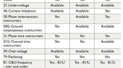
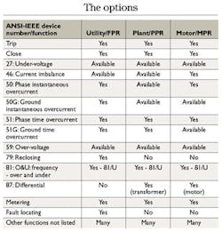
Table 2. Protective relaying functions.
Meet the protective relay
According to IEEE 100, a protective relay is a device that detects defective lines, apparatus and other abnormal or dangerous power system conditions and initiates appropriate control circuit action when it does. The most common protective relay is the overcurrent relay that trips a circuit breaker when it senses overloads and shorts. Other relays operate on voltage, frequency, impedance, pressure and temperature, to name a few variables.
Many relays operate with currents and voltages that are proportional to those on the power system. Current transformers (CTs) and voltage transformers (VTs) convert grid currents and voltages into manageable secondary quantities in the range of five amperes and 120 volts. On older relays, these fed electro-mechanical coils, armatures and induction disks to close a contact that tripped the circuit breaker. Modern microprocessor relays manipulate the electrical signals from the current and voltage transformers mathematically and cause a contact to close and trip the circuit breaker. The microprocessor-based relay is a computer and, therefore, can perform other control and protection functions, such as metering, sequencing events and locating faults.
The Northeast power grid had been stressed to its maximum limits and some event started the system "swinging." The protective relays that electric utilities use for isolating faulty parts of the system should have minimized system instability and prevented the cascading blackout. But, for whatever reason, the whole electric grid started swinging.
The subsystems couldn't be separated from each other. The generators that had excess capacity should have been able to recover from the over-speed/over-frequency condition. Other overloaded system segments were unable to shed loads quickly.
Load shedding
A series of under-frequency load-shedding relays set at various frequencies and time delays can disconnect excess load. For example, under frequency set points may be similar to those in Table 1.
Shedding loads keeps the generators on-line by matching capacity to load. When a utility is overloaded or has insufficient generating capacity, the frequency decays. Quickly shedding small amounts of load at 59 Hz to 59.5 Hz may restore the match. However, if the frequency decays below 59 Hz, even more load must be removed to restore balance quickly and prevent the generators from tripping off-line.
A load-shedding program must be pre-planned and initiated automatically. The timing shown in Table 1 is in the range of 0.1 second to 0.2 second before corrective action takes place, much faster than any human can react.
Functionality
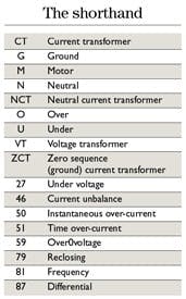
Protective relay functions are identified by a set of standard ANSI/IEEE device numbers. For example, the frequency relay for load shedding is identified by the number "81," which signifies frequency, and "U," which signifies under. Other common numbers include:
27 - Undervoltage.
46 - Current imbalance.
50 - Instantaneous overcurrent.
51 - Time overcurrent.
79 - Reclosing.
81 - Frequency.
87 - Differential.
Letters often provide additional information about the device number. For example, 51G represents a ground-time overcurrent relay.
Protecting your plant
Northeast utilities are analyzing what went wrong and what worked right. Their short-term investigations will center on protective relaying schemes, just as yours should. Long-term planning will most likely center on adding transmission lines to strengthen the systems, which will upset people who wake up one morning to find a new transmission line next to their house, school, church or factory.
At the local level
A controlled separation of your plant from the utility grid may take the form of a scheduled shutdown, during which the utility opens a circuit breaker or switch. This is normally a manual operation performed at the utility's own switching device. However, most utilities have supervisory control and data acquisition (SCADA) systems that may allow them to open the switching device remotely. An uncontrolled separation is normally performed through circuit protective devices, such as breakers and fuses, using a trip signal that a protective relay sends to the breaker.
If you don't know how the utility is protecting your plant, ask your representative for the details. The utility's protection scheme isolates its system from problems at your plant that could affect the grid. It's your responsibility to protect your own system from abnormal conditions, including those that the utility causes. For example, if the utility has a single-phase condition, your devices must keep your equipment from being damaged. The most common form of damage from single-phase is motor damage. While OEM motor overloads provide some protection, other protective relays can, and do, provide better protection.
Ground fault protection is the most common electrical failure on a utility or industrial power system. It's been estimated that more that 85 percent of faults involve ground, and many multi-phase faults originate as a ground fault.1 Therefore, understanding system grounding and ground fault protection is important. Each of the following protection schemes includes ground fault protection as one of its key elements.
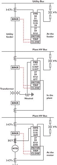
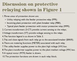
Utility feeder breaker protection is shown in the upper part of Figure 1. Utility feeder protective relays (FPR) typically consist of a number of common relaying and control functions listed in Table 2. The feeder protective relay normally has overcurrent tripping functions; various control functions, such as tripping, closing and reclosing; and fault location. Some utilities include indicating metering, under-frequency load shedding, SCADA and other functions.
Protect three locations
Figure 1. Feeder, plant and motor protection.
Plant breaker protection is shown in the center of Figure 1. The normal line of demarcation between the utility and the plant is at the utility revenue meter. Plant owners are responsible for protection downstream of the metering point. The plant feeder protective relay (PPR) can take on a number of functions, with overcurrent protection as a minimum. However, the plant breaker shown in Figure 1 protects the plant as well as the transformer. In particular, phase and ground overcurrent protection are provided as a minimum. Transformer current differential, under voltage, over-voltage and under-frequency protection are other common protection functions.
Motor breaker protection is an example of a typical plant feeder and is shown in the lower part of Figure 1. The internal plant feeder breakers can protect a number of load types. Consider a motor feeder. The motor protective relay (MPR) can take on a number of functions. In the illustration, it protects the motor from motor and system problems. However, another function not shown is limiting the number of starts per hour.
An optional relay shown in each of the schemes is the 81-U relay, which is the under-frequency relay. When utility systems become unstable and start splitting up, some systems will have an abundance of generation capacity and likely generate an over-frequency condition. Governor controls usually bring the frequency back to normal. Other systems become generation-deficient and the frequency decays. If load is not shed, the system will fail. By proper application of the under-frequency relay to shed load on the utility system, sufficient load can be dropped, generation saved and service restored to the loads in minutes, not hours as occurred in the northeast blackout.
Table 3. Abbreviations applicable to protective relays.
Many utilities have pre-selected the loads to be shed by under-frequency. Your plant may be shed at a utility substation, at the feeder or at the transformer level. Many utilities may be adding under-frequency load-shedding schemes as a result of the northeast blackout. If your plant's load is sufficiently large, the local utility may require your plant to shed load. If you have concerns or questions about your plant and load shedding, contact your local utility.
The northeast blackout was unfortunate and should not have happened. An aging electric grid, an inadequate transmission system and poor performance of dispatchers will likely share the blame. More government bureaucracy will be the result. There is little that can be done at the plant level to have an impact on the ultimate solutions.
However, you can learn from the Northeast blackout and take a closer look at your plant's electrical system. Most companies won't spend money on an existing electrical system. It's not an approach that's in vogue today, instead they're downsizing, canceling capital projects and delaying electrical maintenance.
However, it's important to take a long-term view. Ensuring that you have the proper and necessary protective relays will not only protect your systems, but help to operate, control and maintain it. Reviewing protective relaying schemes for both your plant and your utility may prevent either of you from fading to black.
John P. Nelson, P.E. is President and Project Manager at NEI Electric Power Engineering Inc., Arvada, Colo. He can be reached at [email protected] and 303-431-7895.
