Many batch and semi-batch processes in the chemical industry require both heating and cooling from the same equipment, such as a jacketed reactor. Operational simplicity often requires the same heat transfer fluid (HTF) for both services. Some unique design considerations include:
|
View more content on PlantServices.com |
- Specific heat and density properties over the full temperature operating range.
- Vapor pressure at the high end of the temperature range.
- Viscosity and pumpability at the low end of the range.
- Maintaining the mass balance between cold and hot loops.
- Overall cost.
- Plant preference.
Design alternatives
Systems that must heat and cool often use the same HTF because using different HTFs may require separate coils, separate heating and cooling jacket zones, or outside heat exchangers, each of which complicates mechanical design. Different HTFs may be used in a common jacket, but operations are complex because the fluids must be drained before changeover from heating and cooling and back again. An examination of alternatives using a jacketed vessel illustrates some approaches and challenges.
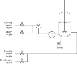
One approach (see Figure 1) uses steam to heat and water to cool a process vessel directly. This system works, providing the required cooling temperature doesn't fall below the freezing point of water. However, the jacket must be drained when switching from cooling to heating. Additionally, the cooling water isn't normally suitable as boiler feedwater and must be segregated from the condensate return. Cooling water must be drained from the jacket first. Any remaining steam condensate after a heating cycle can be mixed with the cooling water, assuming the boiler feedwater additives are compatible with the cooling water system.
Figure 1. This direct approach uses steam to heat and water to cool a process vessel.
Other HTFs can be used in a vapor phase for heating and in a liquid phase for cooling, assuming the HTF can service the full operating temperature range. If a suitable HTF is available, then a common drain/return system could be used.
When heating and cooling services require different HTFs, they usually must be segregated physically. The system in Figure 1 also could use different HTFs for heating and cooling, but each would have to be drained before the switchover, and each must tolerate some cross-contamination. Operational delays and cross-contamination during switchover normally render such a design impractical.
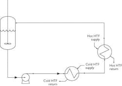
Another method uses a circulating loop that passes the circulating process fluid through heat exchangers in series (see Figure 2) with one heating the fluid and the other cooling it. This solution is more mechanically complex than the first approach, but offers some advantage in that the heat exchangers may be designed without vessel geometry or jacket area acting as design limitations.
Figure 2. This approach uses a circulating loop that passes the process fluid through series heat exchangers.
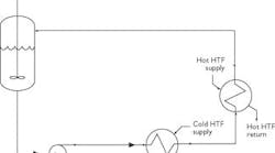
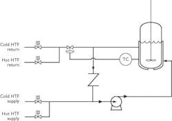
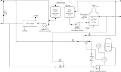
When the required heating and cooling temperatures are within the service range of a single fluid, a variation on the first approach may be used (see Figure 3). A circulating loop is fed cold HTF for cooling service and hot HTF for heating service. Because these HTF supply loops are interconnected, HTF liquid levels may vary during switchover because the fluid transfer from one loop to the other goes through the tempering loop. Most systems are naturally self-correcting because heating and cooling cycles balance the mass transfer between loops. However, an open balance line may be provided between the expansion tanks.
Figure 3. This scheme works if the required heating and cooling temperatures are within the service range of a single fluid
Because of the range of HTFs available, design and operational approaches, and the system cost, owner and operator preferences strongly influence system design. A system using steam and water may be the least expensive solution, but may limit operations. A common non-aqueous synthetic HTF may provide the most flexibility and reliability, but may require a premium-cost HTF to achieve the desired temperature operating range. Process requirements, system cost, operability, safety, reliability and end-user preferences must be balanced.
HTF selection
A critical design issue is finding a single heat transfer fluid with stable, acceptable properties at both high and low temperatures. It must not boil, freeze or decompose (vapor systems are drained of liquid cooling fluid during switchover). Some synthetic HTFs with acceptable properties have low flash points and pose fire hazards. Some have unacceptable odors, which may disqualify them from use in hygienic or sterile settings, such as pharmaceutical production facilities.
If a suitable single fluid cannot be found, then separate fluids (with the attendant mechanical and operational complexities) must be considered.
System considerations
Figure 4 is an example of a system using a single HTF for both heating and cooling. Chillers supply cold HTF for various process-cooling needs, such as the reactor and vessel jackets, overhead condensers and vacuum pump condensers. A single pumping loop is furnished for chillers and distribution system. A single pump loop system must satisfy chiller flow requirements and manage system HTF demands. Cold HTF returning from the distribution loop is routed directly to the cold HTF pump's suction while pumps in the distribution loop send HTF through the chillers to cold HTF users through distribution headers. The HTF flow rate through the chillers is fixed. At start-up, the system is filled from the low point and vented from the high points.
Figure 4. An example of a complete system using a single HTF for both heating and cooling.
Multiple chillers often are paired with a dedicated loop pump. Chillers and their corresponding distribution loop pumps operate on the basis of temperature loads. Cold HTF pumps often are placed on the emergency power system to provide cooling during power outages. Bypass valves located at each end of the distribution header branch maintain the cold HTF supply temperature during low demand. It's important distribution header temperatures be maintained to avoid prolonged lag times at the beginning of heating or cooling cycles. Rather than rely on bypass valves at the end of the header, bypass valves often are provided at the chiller discharge to maintain the required flow during low-demand periods. In such systems, a small bleed-through orifice is used at the distribution header to maintain header temperatures.
The cold HTF expansion tank must accommodate the cold HTF as it warms during shutdown. Locate the expansion tank at the system's high point to allow for proper venting when filling the system. If it's located at a lower point, increase the expansion tank operating pressure to allow for the static head of liquid within the system during operation. Ensure adequate freeboard to accommodate cold HTF volume that drains back during shutdown. Always fill the system through its low point.
The hot HTF system supplies process-heating needs, such as vessel and reactor jackets. A single pumping loop supplies the distribution system. Hot HTF pumps often are placed on the emergency power system to permit operation during power outages. Hot HTF returns from the distribution system through the hot HTF expansion tank. The tank features a continuous flow-through design that maintains a high operating temperature during start-up to evaporate water that may be present in the system. After start-up, the tank is bypassed and allowed to cool to ambient temperature. An open equalization line allows for system mass and temperature variations during normal operation. The design requires sufficient surge capacity (usually 3 to 10 minutes) in the expansion tank to prevent starving the circulation pump.
Hot HTF loop pumps move fluid through the heater and to the distribution system. HTF flow through the heater is held constant because low flow may cause localized high film temperatures, resulting in HTF charring or degradation. Degradation takes two general forms. The first is low-boiling volatile materials that act as non-condensables to be vented through the expansion tank blanket system. The second form is tarry residues that cause coking-type fouling.
Bypass valves located at the end of each distribution header branch maintain high fluid temperature during periods of low demand. An alternative is to provide bypass valves at the heater discharge to maintain the full flow required at the heater during periods of low demand to avoid reliance on the end-of-header bypass valves. In such systems, a small bleed-through orifice may be used at the distribution head to maintain header temperatures.
HTF expands as it warms. Locate the expansion tank at the system's high point to allow for proper venting when filling the system. If located at a lower point, increase the expansion tank's operating pressure to allow for the static head of the liquid in the system during operation, and ensure it has adequate freeboard to accommodate the volume of hot HTF that drains back during shutdown. Always fill the system from its low point.
Locate the hot and cold HTF expansion tanks adjacent to one another for convenience. Doing so minimizes the length of balance line that connects them. This line allows both to share a common inert blanket and allows HTF to pass back and forth to balance the HTF volume between the two systems naturally.
Tempered HTF loops at each user maintain the setpoint temperature by drawing from the appropriate cooling or heating headers. The required heat transfer rate and available heat transfer area determines the loop recirculation rate. HTF is bled out of the user loop through a temperature control valve, allowing fresh HTF to enter the loop hydraulically and maintaining required loop temperature. Remotely actuated block valves isolate the tempered loop from the cold and hot HTF systems and shut off the unused system portions from the tempered loop.
During switchover, HTF from the tempered loop bleeds back to the distribution loop being brought into service, which transfers the mass to that loop. When this transfer becomes large enough, the levels in the cold and the hot expansion tanks change, requiring some HTF exchange between loop systems to maintain adequate levels in both. The balance line between hot and cold expansion tanks allows for this exchange.
Water removal
It's important to remove water from the system before putting it into operation because the chilled and hot HTF systems are linked through tempered HTF circulation loops at each user. Rapid vaporization could result in an explosion if water enters the hot HTF system. Also, water in cold HTF systems may freeze, blocking lines, jackets or exchangers. Avoid hydrotesting, if possible, to reduce the chance of water remaining once testing is completed. However, in most cases, hydrotesting cannot be avoided, and the system must be flushed to remove weld slag and other debris. Provide adequate low-point drains and allow time for proper system drying after flushing and hydrotesting.
Water can be removed by draining, dry-air purging and heating the entire chilled and hot HTF system before final start-up. Systems with chilled HTF alone may have a start-up heater to remove water. Adsorbents (one may use silica gel, activated alumina, or molecular sieves) also can be used to remove water.
Final details
A variety of HTF systems offer combined heating and cooling service. System design often requires accommodating owner preferences, rather than following strict process design considerations. In selecting a common HTF, consider the operating temperature range requirements carefully. Consider steps to manage HTF transfer between the two interconnected systems, although such transfers usually balance out as a natural consequence of operations in a batch process. Take special care to remove water from non-aqueous HTF systems, especially the cold HTF system.
Bill Tuck is a principal process engineer with the Energy and Chemicals business unit of Fluor Daniel, Inc. He can be reached at [email protected].
