Build on your safety structure with functional safety
Change is constant. That’s especially true when you’re talking about machinery safety standards. Though safety standards have continued to change throughout manufacturing history, the most recent wave of revisions enhance our way of thinking when it comes to machine safety designs.
Historically, most standards have been prescriptive in nature and have provided guidance about the structure of control systems to ensure they meet the safety requirements. By using the principles of redundancy, diversity and diagnostics, levels of safety system “structures” were conceived to help ensure that the safety function would be performed. But an important element was missing.
Every safety system uses the basic premise that there exists a finite possibility of failure. Some of those failures might be safe, but some could lead to danger. If you asked machine operators whether they would be more comfortable with a Category 2 (a single-channel) safety system or a Category 4 (redundant) safety system, they’d most likely answer Category 4. But, if you asked again whether an operator would be more comfortable with a Category 2 system that is likely to fail to danger once in 30 years or a Category 4 system that has a mean-time-to-dangerous-failure of only one year, you might get a different answer. The missing element is time. Essentially, the time element adds a confidence factor that the safety system is going to perform properly today and tomorrow. In other words, we have more information and, therefore, more confidence about the safety function’s reliability.
| Hardware fault tolerance | |||
| Safe failure fraction (Diagnostics) |
0 | 1 | 2 |
| <60% | ---- | SIL1 | SIL2 |
| 60% - <90% | SIL1 | SIL2 | SIL3 |
| 90% - < 99% | SIL2 | SIL3 | SIL3 |
| ≥99% | SIL3 | SIL3 | SIL3 |
Table 1. The safety integrity level (SIL) is a function of fault tolerance and failure rates. |
|||
Applying time to standards
Functional safety builds on the existing safety structure approach by adding a time element. This element is known as the probability of dangerous failure, and its inverse is called the mean-time-to-dangerous-failure. This time element causes more upfront pain for safety component suppliers, but should result in less pain for machine operators and — surprisingly — safety system designers.
Before we get into this, we must discuss two important standards: ISO13849-1:2006 and IEC62061:2005. Both apply the time element to machinery safety systems. ISO3849-1:2006 builds on the “categories” of safety structure, whereas IEC62061 builds on the foundation of the categories. This is called hardware fault tolerance. A third element, not new at all, has been added to the picture to give safety system designers more flexible, less painful ways to meet the safety requirements. This third element is diagnostics. Putting these three elements together yields a time-sensitive level of integrity in a safety system. IEC62061 uses the term safety integrity level (SIL). Only three SILs apply to machine systems: SIL1, SIL2 and SIL3. ISO13849-1:2006 uses the term performance level (PL), and these use the alphabet, PLa through PLe.
How it all comes together
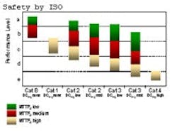
Starting with IEC62061, the secret is given away in Table 1.Figure 1. The performance level is a function of the mean-time-to-dangerous-failure and the diagnostic coverage.
Suppose the risk assessment determines that a SIL2 rating is needed. Table 1 gives three options for achieving SIL2. The trade-off is hardware fault tolerance with diagnostics. With zero fault tolerance, 90-99% of the failures that occur must be safe failures. If a single-channel system with appropriate diagnostic is too difficult or expensive to achieve, then a single fault-tolerant structure with less diagnostics can be tried. The third alternative is a two fault-tolerant system with little or no diagnostics (less than 60% safe failures). Similarly, ISO13849-1 reveals similar relationships in Figure 1.
For example, let’s assume the risk assessment demands a performance level D. Figure 1 reveals four alternatives. A Category 2 (zero fault tolerant) structure with a very high mean-time-to-dangerous-failure and low diagnostic coverage might be the least-expensive solution. At the other end of the spectrum, a Category 3 (single fault-tolerant) system with medium diagnostics might turn out to be the ideal solution. This gives designers what they need: flexibility to achieve their safety requirements.
Minimizing potential for systematic faults
Functional safety doesn’t stop at random hardware failures. Additional elements also must be taken into consideration, such as common-cause failure. This particular element has been discussed in standards going back to at least the 1980s. Functional safety takes the discussion to the next level. Functional safety applies a scoring system that attempts to influence the safety system design to minimize the potential for systematic faults. A certain point value is awarded for steps such as segregating signal paths, having design expertise, considering environmental compatibility and the designer’s training and competence. Accumulating a specific number of points is considered as having achieved adequate protection against systemic failures. The concepts are the same, but the scoring values differ between IEC62061 and ISO13849-1:2006.
| IEC 61508 is the IEC standard that addresses the functional safety of electrical, electronic and programmable electronic safety-related systems. The main objective of IEC 61508 is to use safety instrumented systems to reduce risk to a tolerable level by following the overall, hardware and software safety life cycle procedures and by maintaining the associated documentation. Issued in 1998 and updated in 2000, it has since come to be used mainly by safety equipment suppliers to show their equipment is suitable for use in SIL-rated systems. |
| IEC/EN 62061:2005 is the IEC standard covering the functional safety requirements for electrical, electronic and programmable electronic safety-related systems for the machinery sector of the marketplace. Machine suppliers or safety system integrators should either use this standard or ISO13849-1:2006. |
| ISO EN13849-1:2006 is the ISO standard covering the functional safety requirements for electrical, pneumatic, hydraulic and mechanical safety systems. Machine suppliers or safety system integrators should either use this standard or IEC62061:2005. |
Safety component suppliers, on the other hand, accept more of the burden of functional safety. Each component in the safety system must have an assigned probability of dangerous failure or mean-time-to-dangerous-failure. Currently, this type of information often is unavailable. Many product design standards are being modified to define the criteria for dangerous failure, testing requirements and the statistical tools that determine the time-to-dangerous-failure. At that point, many months of testing are required to confirm the achieved level.
For example, take an electromechanical component with an expected number of cycles-to-dangerous-failure of two million operations. This is called the B10d value — the number of cycles before 10% of the sample lot fails to danger. If the test cycle is two seconds ON and two seconds OFF, complete testing will require at least 92 days. In practice the device under test may not exhibit a dangerous failure because they fail in a safe direction first.
Other statistical methods may also be suitable. Component suppliers might terminate their product testing after achieving a sufficient number of successful cycles and not necessarily test to failure. They estimate the B10d value based on the successful cycle count and an assumption that half the failures in the field will produce a dangerous situation. As a fallback position, ISO13849-1 has default values that can be used if no other values are available.
The safety system designer doesn’t get off without some effort. The designer must gather functional safety data from component suppliers, connect the components into a workable system and determine either the system’s Safety Integrity Level or its Performance Level. Although this isn’t a daunting task, computerized tools will soon be available to simplify this step.
The machine safety world continues to evolve to provide even safer machine control systems and more flexibility to achieve those safer designs. These changes will take some time to become widely implemented, but, as they say, “The train has left the station.” The change has started. Safety component suppliers are definitely busy. Machine suppliers now must become aware of functional safety and how to take advantage of its benefits.
Steve Dukich is senior application engineer at Rockwell Automation in Chelmsford, Mass. Derek Jones is part of Rockwell Automation in the United Kingdom. For more information, please contact Tanja Bartulovic, Rockwell Automation, [email protected] and (440) 646-4117.

