Don't gamble with control safety and reliability
As a wise singer once crooned, you have to “know when to hold ’em and know when to fold ’em.” But Kenny “The Gambler” Rogers merely had to beat long-shot odds to win at his game. Outside the casino, designers of industrial control systems don’t have the luxury of being right only 51% of the time. For many manufacturing and process systems, a control system failure — even for a second — simply isn’t an option. Hence, it’s important that control systems deliver safe and reliable performance, even when things go wrong.
[pullquote]Also important is the need to maintain production uptime; while additional control devices help prevent accidents, they also reduce uptime by increasing opportunity for nuisance trips. You need to find that delicate balance between safety, production reliability and overall cost when designing, operating and upgrading production control systems.
The established concepts of safety and reliability for industrial controls are detailed in ANSI/ISA 84.1, Application of Safety Instrumented Systems for the Process Industries. This ANSI/ISA standard applies within the United States and is equivalent to the IEC61511 standard in Europe and other areas. These standards reveal that statistical analysis of safety instrumented systems is a science in itself. Fortunately, only a few basic concepts are required to appreciate the simplified discussion presented in this article.
Safety in numbers
Although using only a single control device often is appropriate, much of safety instrumented system (SIS) design incorporates multiple devices to perform a single control function. The multiple units are cleverly arranged to accommodate the anticipated failure of any single device. Although formal terms such as replicated, complementary or diverse aptly apply to the various arrangements, the catchall term “redundant” is normally used to describe any flavor of multiple-device configuration.
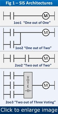
The SIS concept uses an “M out of N” terminology to describe device configuration; reliability is based on M number of properly functioning components out of a total of N. This concept often is noted as MooN (spoken as “M out of N”). For example, 1oo2 (“one out of two”) might represent an arrangement of two relays in series; depending on context, this arrangement can safely shut down a process with only one of the two devices, or it can continue safe operation with only one of two. The terminology for each context is the same, but the applications are quite different. Further examples of typical SIS architectures include:
- 1oo1: A single fuse or rupture disk that limits an over-current or over-pressure malfunction in a near infallible mode.
- 1oo2: Two power supplies connected in parallel to accommodate shutdown of either one. Only “one out of two” is required for continued safe operation.
- 2oo2: Two high-level sensors connected in series that permit a tank inlet valve to open. “Two out of two” devices, both indicating there is no high level, are required to safely open the valve.
- 2oo3: Triple modular redundant (TMR) pressure transmitters configured in a voting system. “Two out of three” devices must agree to continue safe production should one of the three transmitters fail in any manner.
Figure 1. These relay contact motor control schemes show how the degree of reliability desired determines the degree of complexity needed in the control system.
Note that each of these examples addresses a specific malfunction of a control device. This important concept will be explored a bit more later on. Figure 1 illustrates four examples of increasingly complex SIS architectures; all are based on simple relay contact motor control.
Demanding reliability A key SIS concept used to evaluate reliability is called probability of failure on demand, or PFD. Its calculation is complex, and often controversial, but is simplified here to denote the percentage of time that a device is expected to not perform its control function properly. As with golf, the goal with PFD is a low score.
Different levels of PFD might apply to the same device based on its role in the overall system. For example, a pressure sensor might have a 4% probability of causing a nuisance trip, but only a 2% probability of causing an unsafe situation. Because these probabilities are calculated on a per year basis, and accumulate over time, a device with a 4% PFD is estimated to malfunction once every 25 years (4% failure/year x 25 years = 100% failure). And because the PFD is estimated for each device, the net reliability of a total system rapidly decreases if multiple devices affect a single control function. Therefore, low PFD values for each device are prime design criteria.
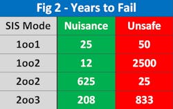
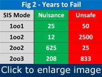
{pb}Figure 2. Redundant schemes 2oo2 and 2oo3 help avoid nuisance trips, but risk more frequent unsafe failures than the simpler 1oo2 scheme.
The values shown in Figure 2 compare the reliabilities (expressed in years to fail) obtained with typical SIS architectures. These values assume a single component with PFDs of 4% nuisance and 2% safety, as mentioned above. The 1oo2 values represent the reliability of a single device. Those numbers might be adequate for some situations, but they degrade rapidly when multiple devices affect a single system.
For redundant device configurations, it’s interesting to note that the simplest configuration, 1oo2, has the longest time span during which an unsafe condition is expected to occur. However, it also has the shortest time for a nuisance trip. Systems that require reliable operation as well as avoiding unsafe situations might be better served by more sophisticated solutions as found in the 2oo2 and 2oo3 modes.
Hold ’em or fold ’em
Two design philosophies for accommodating predictable failure are called fault-tolerant and fail-safe. Although these schemes are first cousins, they represent two distinct responses to a control malfunction. The fault-tolerant mode will “hold ’em” and let the control function continue to operate correctly. The fail-safe mode, however, will “fold ’em” and admit defeat while safely ceasing normal operation. Both modes have valuable — but different — roles in reliable control system design. The following simplified definitions (adopted from the SIS standard) highlight the similarity and difference between the two control concepts:
- Fault-tolerant: Continued correct execution in the presence of a specific malfunction.
- Fail-safe: Assumes a predetermined safe state in the event of a specific malfunction.
www.hima.com
www.triconex.com
www.icstriplex.com
The similarity between the fault-tolerant and fail-safe modes is their delivery of a predictable response to a specific malfunction. The difference between the two modes lies in their responses; fault tolerance maintains the normal control function, while fail safe ceases normal operation in favor of an acceptable safe state. Note that both control modes require some portion of the overall affected system to remain functional. A control design that continues predictable operation after it itself has totally failed is neither reasonable nor reachable.
Identification of specific malfunctions that require a predetermined response is another key aspect of failure-mode design; neither mode by itself can provide a predictable reaction to unknown or indeterminate malfunctions. Specific predictable malfunctions must first be identified such that a failure mode can be designed to accommodate them.
Fault tolerance
Generally speaking, no single device can provide a fault-tolerant control function. Most often, a combination of similar (or identical) devices is required to provide “replication” of a particular role such that they perform the same function independently. ANSI/ISA 84.1 labels this as “redundant” if the replicated functions are identical. An alternate method is called “diversity,” in which devices perform similar control functions by means of different technology, process interface points or computer features.
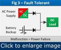
Figure 3. If the main power source, the AC-to-DC supply, fails, the system continues to operate because the battery backup remains functional.
Figure 3 represents a simple 1oo2 fault-tolerant system in which an AC-to-DC power supply is paired with a battery backup to power a DC load; this arrangement uses two so-called diverse components that provide fault-tolerant operation for the specific malfunction of power source failure.
More elaborate fault-tolerant examples include replicated input/output systems and logic solvers that use a 2oo3 voting scheme to accommodate I/O or processor malfunctions. These examples represent both ends of the fault-tolerance spectrum. Such robust designs are appropriate for industrial processes that can’t withstand abrupt suspension and for any safety system that demands the highest level of reliability.
As shown in Figure 2, 2oo3 voting systems promise the longest duration without nuisance trips while maintaining safe operation. That high-end performance comes at relatively high cost, although currently far less than when the concept went mainstream several decades ago. You can minimize total system cost by applying the principles of ANSI/ISA 84.1 and other related standards in a consistent and organized manner. Careful partitioning of the overall control and safety system isolates the critical process controls that require advanced SIS concepts.
Fault tolerance certainly isn’t appropriate for every control loop in a plant, but nearly every production environment can benefit from targeted application of a non-stop and safe control system design.
Fail-safe
While fault tolerance grabs most of the trade press, fail-safe controls still serve as journeymen in many control system designs. Continued normal operation, however, typically isn’t the goal of a fail-safe mode; the role of fail-safe is to place the control function in a predictable state in which other control functions can operate the ongoing process safely. So, although the control function has technically failed, safe overall process operation isn’t compromised in a fail-safe control system.
{pb}Fail-safe designs proudly say, “Sure, I might break one day, but I’m not taking anyone down with me.” Consider the lowly electrical fuse; it gives its life in the name of safety by preventing an over-current condition that could cause a fire, or worse. The affected process, however, must tolerate a total loss of power if it’s to rely on a simple fuse for protection.
However, many control situations demand a more sophisticated fail-safe solution to a specific malfunction, such as safely withstanding a loss of control power or input signal. The most common fail-safe actions are fail closed or fail open, in which the device output is forced open or closed when a specific malfunction occurs. Other options include fail-in-place and fail to a specific value. These fail-safe actions permit the still-functioning device to place a controlled element, such as a throttle valve, into a predetermined state to maintain overall process safety.
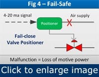
Figure 4. A spring-loaded positioner closes the process valve if the pneumatic air supply fails.
Consider a current-to-pneumatic positioner shown in Figure 4. The local controller is designed to fail-closed on loss of pneumatic motive power; if the air supply fails, a spring inside the positioner automatically closes the valve, regardless of 4-20 ma input signal. Note that the positioner’s fail-safe feature doesn’t apply to failure of the positioner itself; the feature instead covers the specific malfunction of an external power source. Failure of the positioner itself would be a different specific malfunction that must be covered by another device. You must understand this important concept and apply it when using any device in a fail-safe situation. First determine the specific malfunction, then select control components that can remain operational while covering for that anticipated failure.
Play your cards right
Fault-tolerant and fail-safe designs clearly serve an important role in reliable control system design. Understanding the complexity, benefits and costs of each mode is essential to keeping important processes safely online with the uptime demanded in high-production environments. Sometimes a few dollars of fail-safe control can prevent dangerous situations that harm people, property and the planet. But those safety dollars also must prevent nuisance trips that can lead to costly lost production. Proper application of fault-tolerant and fail-safe designs are, therefore, vitally important when designing and maintaining process control systems. Every control function must be considered carefully because, as ole Kenny advised, you have to know when to hold ’em and know when to fold ’em.
Special thanks to Richard Roth with HIMA Americas, Inc., for assistance with this article.
Arthur Zatarain, P.E., is an engineering and operations consultant in Metairie, La. Please contact him at www.artzat.com.
