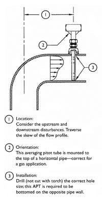
Installing an averaging pitot tube is a simple process. However, problems can result that are difficult to correct later if a few basic factors are not considered during the mounting process. The first three steps to successful mounting are location, orientation and installation.
Some pitot tubes have hardware to support its far end. Tack weld such hardware with the pitot tube in place before performing final welds.
Step one: Location
First, determine if adequate straight run is available. Straight run refers to the amount of obstruction-free piping upstream and downstream of the averaging pitot tube. Elbows, control valves, changes in pipe size and other obstructions create flow disturbances that affect accuracy. Because the averaging pitot tube measures and averages the readings from multiple points along the flow profile (see Figure 1), its straight run requirements are less stringent than most other devices, but upstream and downstream disturbances must still be taken into consideration.
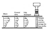
Figure 1. Examples of flow profiles
Most flow meter manufacturers publish straight run charts. However, the charts dont tell where to locate the pitot tube when adequate straight run is not available. Intuition may not always be correct when deciding. For example, when the only option is to install it immediately downstream of an elbow, one may be tempted to install it as far away from the elbow as possible. While its true that upstream disturbances influence accuracy more than downstream disturbances, this is one case where installing the averaging pitot tube two diameters from the centerline of the elbow is best (see Figure 2).
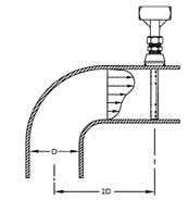

Figure 2. Elbow mount installation
The velocity profile hugs the outside radius of the pipe immediately after an elbow in a predictable manner. At two pipe diameters from the centerline of a short-radius elbow, reasonable accuracy can be achieved if the instrument is mounted to the outside radius of the elbow and the flow coefficient is properly adjusted.
Notice how the pitot tube traverses the skew of the flow profile in Figure 2. If it were rotated 90 degrees from the position shown, it would not average the flow correctly. Another example of traversing the skew occurs downstream of a butterfly valve, with the instrument oriented 90 degrees from the valve axis.
Not all straight run rules are chiseled in stone. For example, the chart may require 24 pipe diameters after a valve. However, a fully open, full-throat gate or ball valve induces only a small flow disturbance. A modulating control valve or butterfly valve causes a much greater flow disturbance. Because there are so many combinations possible, consult the instrument manufacturer for a recommendation on where it should be installed and for an estimated accuracy. One pointer: always provide a sketch or diagram. Verbal descriptions are not always conveyed or interpreted accurately. In addition, there may be something in the diagram that seems irrelevant, such as a temperature sensor or pressure tap, but may affect the accuracy of the device.
Step two: Orientation
Consider horizontal piping runs first. For gas applications, mount the pitot tube in the upper 160-degree portion of the pipe to prevent condensate from collecting in the instrument lines or transmitter (see Figure 3). This is especially critical when the gas is saturated or operating at a temperature above ambient.
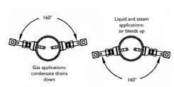
Figure 3. Horizontal pipe orientation
For liquid applications, the pitot tube should be mounted in the lower 160-degree portion to prevent air from collecting in the instrument lines or transmitter. Because steam applications require liquid legs to isolate the transmitter, the same consideration applies.
For vertical piping, mount the pitot tube in any location around the circumference of the pipe. For gas with a high moisture content, mount the instrument at a five-degree angle to allow drainage (see Figure 4).
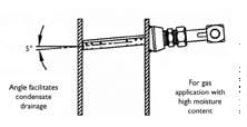
Indicate if the line is vertical when you order the device. The manufacturer will orient the connections parallel to the ground to eliminate low points for condensation build-up.
Non-standard orientation
Occasionally, its not practical to mount the pitot tube in the recommended orientation. For example, a buried water line does not allow access to the lower portion of the pipe; therefore, the instrument must be mounted to the top. In such cases, special mounting considerations prevent entrained air from collecting in the instrument lines or transmitter (see Figure 5).
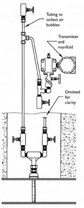
Figure 5. Buried water pipe
Step three: Installation
An averaging pitot tube can be installed through various connections. The two most common methods are flanged and threaded. Regardless of the connection size or type, the size of the hole drilled in the pipe is critical to measurement accuracy.
Hole size
The averaging pitot tube is designed to pass through a specific hole size. For example, if the pitot tube diameter is 7/8 in., the manufacturer will probably recommend a 1 in. hole. In short, the hole should be just large enough to allow the instrument to pass and be de-burred whenever possible. Drilling an oversized hole or using a cutting torch affects accuracy. A large or jagged hole produces a disturbance that can wash out the signal from the sensing ports located closest to the pipe wall (see Figure 6).
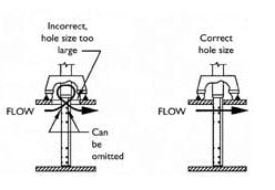
Figure 6. Hole size effect
In smaller line sizes, the sensing ports are located closer to the pipe wall. The smaller the pipe and the larger the hole, the greater effect on accuracy. To quantify the error, for example, a 1-3/8 in. hole in a 6 in. pipe to pass a 7/8 in. pitot tube will generate a potential error of 8 to 10 percent.
If there is an existing oversized hole in the pipe but no alternate mounting location, it is better to have the manufacturer refrain from drilling the sensing ports closest to the pipe wall. While this sacrifices some averaging capabilities, the effect on accuracy is far less than having sensing ports in the swirl zone. As the pipe gets larger and the sensing ports move farther away from the pipe wall, the effect of a large hole diminishes.
Too often, the hole size is ignored, especially when the fitting is welded to the pipe by a contractor working without installation instructions. A common mistake is burning out the hole to match the inside diameter of the fitting. For example, a 1 in. FNPT 3000# threaded weld coupling actually has an inside diameter of 1-5/16 in. Burning out this hole instead of drilling the manufacturers recommended 1-in. hole can introduce a significant error.
Simply specifying the connection size for the pitot tube is not enough. The specification sheet and submittal and certified drawings should identify the hole size as well. Its imperative that this information be passed to the relevant pipefitters and subcontractors.
Another common error is overlooking the pipe schedule. For example, a 6 in. Sch 40 pipe has an inside diameter five percent greater than a 6 in. Sch 80 pipe. Not only would specifying the wrong schedule cause the averaging pitot tubes sensing ports to be positioned incorrectly in the pipe, there would be a flow rate error of 11 percent from the differences in flow area. For pipe sizes 12 in. and larger, the inside diameter of schedule standard pipe is different than Sch 40 pipe. Because Sch 40 and schedule standard are identical up to 12 in., it is commonly (and mistakenly) assumed that they are identical in larger lines. Verify pipe size and schedule before ordering the averaging pitot tube.
Threaded connections
An averaging pitot tube mounted through a threaded connection should be bottomed firmly against the opposite wall of the pipe. This ensures the sensing ports are aligned properly in the flow stream and the pitot tube has structural support. Figure 7 shows why an averaging pitot tube that is not bottomed against the opposite wall has sensing ports lost in the pipe wall.
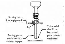
Figure 7. Improper installation
In addition, an averaging pitot tube that merely is cantilevered in the flow stream is structurally weak. A cantilevered pitot tube withstands approximately one-half the velocity of a firmly bottomed pitot tube. The leading cause of pitot tube breakage is leaving it cantilevered in the flow stream. Some manufacturers offer a spring-lock mechanism to ensure the pitot tube is firmly bottomed.
Some pitot tubes have hardware to support its far end. Tack weld such hardware with the pitot tube in place before performing final welds.
Flanged connections
Severe service applications, such as high-pressure steam and explosive gases, usually require flanged connections. Some companies, especially refineries and power plants, require flanged connections throughout, regardless of service.
Most averaging pitot tube manufacturers supply the necessary flanged mounting hardware with the instrument (see Figure 8). This is desirable because the hardware height determines how the sensing ports align in the flow stream. Pitot tube manufacturers have set dimensions for 150#, 300# and 600# hardware and the pitot tube is located accordingly. For this reason, specify mounting flange to be supplied by manufacturer.
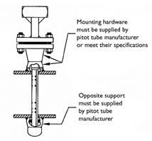
Figure 8. Flanged connection with opposite support
If the mounting flanges are provided by others or if the pitot tube is to be mounted through an existing flange, its important that the flange installation match the manufacturers installation instructions. For example, mounting a 7/8 in. pitot tube through an existing, unused 2-in. 150# flange results in loss of accuracy.
Another consideration when mounting a pitot tube to an existing flange is whether the flange bolt holes are properly aligned. Bolt holes should straddle the pipe centerline, an industry standard orientation (see Figure 9).
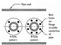
Figure 9. Bolt-hole patterns
The pitot tube flange locates off the bolt hole pattern to ensure it lines up properly in the flow stream. Provide the flange height dimension so the pitot tube can be manufactured according to the specific installation (see Figure 10).
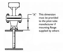
Figure 10. Customer supplied mounting flange
For certain applications, the sensor may be strong enough to be cantilevered rather than with the support hardware. The manufacturer determines the adequacy of the cantilever style based on the flow conditions.
Figure 11 summarizes the most important points of a good installation. If you follow the basics of location, orientation and installation, you can ensure accurate long-term performance.