Gas compression is a common industrial and commercial process. Among its most typical applications are providing compressed air in industrial plants and air conditioning and refrigeration in numerous industrial, commercial and residential systems.
An interesting aspect of the gas compression process is that although while the objective of the process is to increase the pressure of a gas, a significant fraction of the input energy (estimated to be between 80% and 90%) is consumed in raising the gas temperature. When compressing air, about 8 hp of electricity are required to produce 1 hp of compressed air. This provides an opportunity for heat recovery, which in this era of increasing energy costs, can be financially attractive. In the case of air compression, an estimated 50,000 Btu/hr of thermal energy is available to be recovered for every 100 cfm of air provided.
Here some pressure, there some temperature
Without going into the thermodynamic details, don’t equate the temperature rise in the gas being compressed as process inefficiency. A perfectly efficient compression process done on a perfect gas would still exhibit a temperature rise – it’s the nature of the universe we live in. One way to think of it is to imagine that when we add energy to a gas, it gets stored in two separate compartments. One compartment is temperature and the other is pressure. For a given amount of energy added, the fraction that goes into each compartment is a fixed property of the gas being compressed. Inefficiencies in the compression process result in the temperature increasing more than it would for the perfect process.
Also, while the increase in gas temperature with increased pressure can be a detriment, in refrigeration systems, it’s the key element that makes the systems work at all. Low-temperature vapor from the refrigeration system evaporator is compressed and its temperature increases to above ambient levels. This allows the system to reject heat to the outside – which is the whole [i]raison d’etre[i] of the system.
How to cash in
With all that excess energy lying around, you’d think it would be easy to recover some. Amazingly, about 80% to 90% of the input energy is up for grabs, with typical recovery rates between 30% to 90% of what’s available. The determining factors for compressor heat recovery are the same as for any heat recovery process. At a minimum, we need to determine three things: at what temperature is the energy available; at what temperature do we need the energy; and how much of it is there?
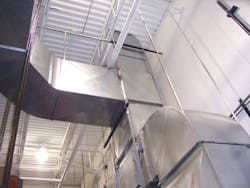
One common way to recover the heat of compression is to duct the air leaving your air-cooled aftercooler or lubricant cooler to provide heated process or space heating air. A booster fan might be necessary to ensure that the pressure drop in the duct doesn’t reduce the air flow across the aftercooler. Figure 1 shows the ducting system used in a manufacturing plant. The arrangement ducts heated air to the plant during the winter and out the roof during the summer.
Seasonal order
Figure 1. Ducting routes heat into the plant in the winter, out the roof in the summer.
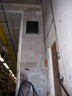
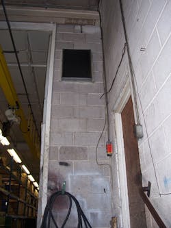
Sometimes, simplicity is the best way to go. In the plant shown in Figure 2, the air compressor is close to the loading dock. All that was needed to recover compressor heat for the dock was a short duct run vented into the dock area.
More comfortable dockers
Figure 2. Ducted heat from a nearby compressor improves working conditions at this loading dock.
Potential heat recovery rates for space heating can be high. The U.S. Department of Energy’s Compressed Air Challenge Source Book (www1.eere.energy.gov/industry/bestpractices/compressed_air.html) [no hyphens] indicates that heat recovery efficiencies of 80% to 90% are common. But remember, you can only recover as much heat as you need. Capturing anything more raises the space temperature above the set point and, unless that’s tolerable, you’ll need to put a thermostatic control on your heat recovery system to duct the excess heat outside.
For a lot of smaller- to medium-sized plants, it’s somewhat redundant to talk about compressor heat recovery for space heating because the compressor is inside the plant anyway and is already providing space heating. What ducting can do is move that heat from a place where it might not be wanted to somewhere that it is.
On the other hand, ducting the compressor’s waste heat outside has a kind of an anti-heat-recovery benefit. Many plants are air-conditioned for quality control reasons, so ducting compressor waste heat outside can save money on air-conditioning. Assuming 50,000 Btu/hr per 100 cfm, the savings would be about 4 tons of cooling, or roughly 6 kW. Multiply that by the number of your cooling operating hours and the unit price of your kWh to get a rough estimate of cooling cost savings.
Do the math
Estimating the savings from heat recovered for use in industrial processes or water heating requires an analysis that considers the temperatures and flow rates involved, as well as the heat exchanger effectiveness. If you assume a heat exchanger efficiency of 70%, you can estimate the amount of heat you can recover once you’ve calculated the minimum product of specific heat and mass flow rate.
As an example, consider recovering heat from 100 cfm of compressed air at 250°F, for use in a process that requires heating 10 gpm of water entering at 70°F. The mass flow rate of air is about 455 lbs per hr, and for the water is about 4,980 lbs per hr. The specific heat of water is about 1 Btu/lb-°F, and for air is about 0.24 Btu/lb-°F. That means that the flow of air has the minimum product of specific heat and mass flow, or about 109 Btu/hr-°F. Multiplying this value by the efficiency (0.70) and the temperature difference (250°F-70°F) gives the estimated heat recovery rate, 13,730 Btu/hr.
Capital costs to implement a compressed air heat recovery system are variable, but the payback period usually is attractive. A quick scan of 25 air compressor heat recovery projects detailed in the Rutgers Industrial Assessment Center (IAC) database indicates an average cost of about $10,400 and average annual savings of about $11,100. Payback periods for the sampled projects averaged about one year with a range from five years to five weeks.
The supermarket effect
Anyone who needs a winter coat when grocery shopping in August or September can get behind the idea of supermarket refrigeration heat recovery. Frequently, it turns out that the interaction of the refrigerated display cases and the store’s HVAC system produces heating loads on the HVAC during the fall, winter and spring. These loads can be partially met by the heat being rejected from the refrigeration system. Energy available for reclaim consists of the display case refrigeration loads and the work of compression.
There are similar opportunities in the industrial arena. Typically, during normal compressor operation, the pressurized refrigerant flows directly to the condenser. When space heating is called for, a three-way valve routes the gas flow to a coil located in the HVAC air handler. Both desuperheating and condensation of the refrigerant gas occurs in the heat reclaim coil. The refrigerant leaves the reclaim coil and flows to the condenser where there is additional heat rejection. It’s estimated that reclaiming refrigeration system heat can have a payback period ranging from about two to four years. Costs for adding heat reclaim to a refrigeration system are estimated at between $150 and $200 per ton of refrigeration system capacity.
Refrigeration system heat recovery is becoming a relatively well understood system design, so implementation is more plug-and-play than air compressor heat recovery. Typically, heat is recovered to provide domestic hot water, space heating or both. There’s a tradeoff to be considered if the refrigeration system uses floating head pressure. Under conditions of low ambient temperature, the demand of the heat reclaim system might require the condensing pressure to be raised to supply more heat. This can reduce or eliminate the head pressure reduction benefits during certain cold weather periods.
Advances in refrigeration system technology are increasing the potential for heat recovery. Because of the mandate to eliminate ozone-depleting refrigerants, designers are exploring secondary fluid loops. These loops are used for cooling display cases and rejecting heat from the system. The secondary heat rejection loop allows easy integration of direct heat recovery or heat-pump heat recovery. In direct recovery, the heat rejection loop is routed through the HVAC air handler on its way to the cooling tower. In indirect recovery, heat pumps on the heat rejection loop extract heat to provide space or water heating – similar to a water source heat pump system.
In a similar fashion, refrigeration compressor (and air compressor) heat recovery can be integrated with geothermal heat pump systems. The geothermal loop is used as the heat sink for the compressors. During the cooling season, the loop rejects heat to the ground. In the heating season, the heat recovered from the compressor supplements the heat extracted from the ground by the ground source heat pumps.
What gets in the way?
Heat recovery is one of the most frequently recommended energy cost reduction measures (ECRM), yet it’s also one of the least often implemented. The biggest reason is that as a retrofit, heat recovery from compressors or any other source usually isn’t a plug-and-play proposition.
Often, there’s some custom engineering involved in sizing the components, setting up the controls and optimizing the integration of the heat recovery with the overall commercial or industrial operation. That’s why heat recovery should be considered early on in the design of a new plant, process or building. That way, the engineering, component selection and controls are part of the initial design effort. This is more cost-effective at the design stage because only incremental costs are involved; there’s no labor or expense for equipment or process downtime, or for disassembly or demolition. Considering heat recovery in the initial design helps ensure that the benefits of this cost-effective technology are realized.
Ben J. Sliwinski is the technical director of the Smart Energy Design Assistance Center (SEDAC) located at the University of Illinois in Urbana-Champaign. He can be reached through the SEDAC Web site at www.sedac.org.


