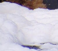
Figure 1. It’s the formation of foam in a close-up picture. You can see the bubbling brown liquid in the top of the picture. Foam can get pulled into the lube circulating system and cause mechanical damage.
Foaming is a fundamental physical property of a lubricating fluid. Foam can degrade the fluid’s life and performance as well as that of the equipment being lubricated. Even though foam performance often is a defined specification for the new fluid, it’s many times ignored on used fluid (Figure 1). The reasons for loss in foam control and the methods of controlling this property in a used fluid should be added to the lubricant specialist’s understanding and knowledge.
Foam in used lubricants has been studied for more than 50 years. It typically forms on a fluid that’s been agitated. The bubbles range from about 10 μm to 1,000 μm in diameter and aren’t uniformly dispersed. They rise to the surface and coalesce to form larger bubbles. As bubble size overcomes surface tension, they break.
Two variables are of interest: foaming tendency and foam stability. The foaming tendency quantifies the amount of foam (in milliliters) that was made during the air introduction and still remains immediately after the cessation of the air flow. Foam stability quantifies the extent to which the bubbles aren’t combining and breaking. In this test, it’s the amount of foam that remains, in milliliters, after 10 min. from the time the air flow is stopped.
Lubricant foaming can lead to serious operational problems. The most common are inadequate lubrication, cavitation and loss of lubrication. However, increased lubricant oxidation, micro-dieseling, control valve losses, spongy hydraulic piston movement and pump oil pressure control losses also can be the results of severe foaming.
There’s often considerable aeration as lubricant circulates through the system and returns to the sump. If the fluid can’t release this air efficiently, it accumulates and causes foam. If foam continues to build, it can cause the oil level to drop until the oil pick-up tube begins to pull foam with the oil.
Summary of test method
A fluid’s foaming property is measured using ASTM D892, which measures foam by three sequences that differ only in measuring temperature. Sequence I measures the foaming tendency and stability at 24°C (75°F). Sequence II uses 93.5°C (200°F). Sequence III uses the same conditions as Sequence I, except it’s performed on fluid that has just been measured in Sequence II. The fluid sample from sequence I is not used in sequence II. The fluid sample used in sequence II is carried into sequence III. There are some antifoam additives that this sequence of test measurement shows significant differences. There are many times the fluids will be seeing sequence II operating conditions.
The antifoam additives require significant high-speed blending to disperse them as small particles. Because of this manufacturing operation, the test standard allows the sample to be treated with a Waring-type blender to redisperse the antifoam additive before running the tests.
The results are reported as two numbers for each sequence. For example: 20/0 means 20 ml of foam tendency was measured after 5 minutes of aeration followed by no foam stability (0 ml) after the 10 minute settling time. Most new oil specifications require 10 ml to 50 ml tendency maximum and 0 ml stability.
Foam morphology
Lubricant foam is an agglomeration of small bubbles, each like a balloon, where equal forces applied in all directions support the sphere. The bubble’s ability to break is related to surface tension and surface homogeneity.
[pullquote]If the fluid has strong interfacial surface tension, the bubble will be strong and tend not to break or coalesce. Thus, foam stability will be long lasting. If the fluid lacks surface homogeneity, it will affect the surface of the bubble. Thus, the forces toward the bubble walls now will be unequal — deforming, weakening and breaking the bubble wall.
Foam bubble strength is directly related to bubble size. Smaller bubbles exert less force against the walls and, thus, are more stable. Stokes Law defines foam stability in relation to the bubble size. In the fluid, the gas bubbles rise, separate and move in accordance with Stokes’ Law. Larger bubbles rise faster than smaller ones. Therefore, the stronger, small bubbles are last to reach the surface. When they do, their behavior depends on the nature of the bubble-surface interface. Modifying the interface to aid in breaking bubbles is the antifoaming agent’s job.
The most common way to increase foam in an aqueous soap solution is to add glycerin. It increases the solution viscosity and forms a weak bond with the water, factors that strengthen the bubble. Lubricant additives and contaminants have the same action. Detergents are a form of soap that often acts as a pro-foamant, wreaking havoc with the oil’s foaming characteristics.
Oxidation products are polar components that often increase fluid polarity and viscosity. Contamination products have been shown to produce stable foam. As they accumulate in the fluid, favorable foaming properties deteriorate. When you observe a lube foaming, always check the fluid’s particle count. Particulates can act as nucleation sites on which bubbles grow. Such bubbles often are the small ones, which are slower to dissipate. Any kind of surface-active contaminant can cause foam and air entrainment. Particles smaller than 4 μm have a similar effect. Apply ASTM Standard D4055-04, Standard Test Method for Pentane Insolubles by Membrane Filtration, using a 0.45 μm membrane to evaluate the fine-solid contamination to determine if there’s a problem.
Antifoams are not all the same
Antifoam additives must balance immiscibility, surface activity and dispersibility. This means they must be insoluble in the fluid so they can spread at the surface/air interface. They also must be readily dispersed into the fluid for long-lasting effects.
The two main antifoam additives are siloxanes and polyacrylates. The siloxane-type is the most common and is the chemistry used in dispersant/detergent packages. This type of antifoam is primarily the dimethylpolysiloxanes; however, other special structures are used that include methylalkyl-, aromatic- and fluoro-siloxanes. There’s even a variety that includes a dispersant to modify the additive’s solubility. These compounds are silicon-oxygen-silicon backbone polymers, rather than the carbon-carbon backbone compounds of the base oil.
Siloxanes often separate
Depending on the fluid, different siloxanes viscosities are used, varying from 1,000 cSt to 10,000, 12,000 and even as high as 60,000 cSt. Based on their molecular weight (and the viscosity it brings) and their insoluble nature, this type of antifoam is introduced into the fluid as a 10% solution in a carrier such as kerosene using very high agitation rates to produce as small a droplet as possible.
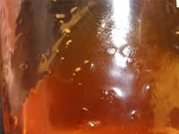
Figure 2. This image shows siloxanes “plating out” on the glass holding the oil.
These additives act on the fluid/air interface. The additive’s surface tension is low with respect to the lube oil and its density also is less than that of the fluid. The additive is insoluble in the fluid, meaning the additive exists as very small droplets on the surface of the liquid when the fluid is static or dispersed throughout the fluid when agitated. These droplets attach themselves to bubble walls to destabilize them. This layer often is thin — a monolayer or partial monolayer of siloxanes is all it takes. The disadvantage of this type of antifoam additive is that it tends to “plate out” on surfaces such as glass (Figure 2) or metallic parts as well as filter media.
If you look at the oil interface on a glass bottle containing a fluid with siloxane-based antifoam, you’ll see this deposition. As you slowly pour the fluid away from the glass surface, you’ll see what look like “fish eyes” on the glass. These are droplets of siloxane surrounded by hydrocarbon fluid. This is the physical operation of the antifoam’s behavior in the fluid and is the same phenomenon that occurs throughout the lubricant system, often decreasing the additive’s efficiency.
- Ensure the mist control system is pulling the proper vacuum listed in the O&M manual.
- Look for leaks that allow air to get into the system — especially at return lines.
- Measure the outflow from the mist control exhaust stack (anemometer should read 1 mph to 3 mph for standard 6-inch vent.) A higher speed suggests a leak.
- Look for fluid plunging from the return lines entering the tank.
- Look for leaks in the body or flanges of the bypass pressure regulators. The high velocity of the fluid leaving the regulator can cause a high vacuum in the line returning to the tank, producing the potential for undetected air leaks in the regulator body.
- Check the flow from the bottom of the demisting packing housing. Install clear tubing if the line is solid. A small drip or trickle is okay; a river spells trouble.
- Check auxiliary equipment connected to the same lube supply. Ensure the return lines don’t let outside air into the equipment in an unfiltered state.
- Ensure there’s some type of trap between the equipment and the return line to the reservoir, or that the line enters the reservoir below the liquid level to prevent free breathing from the vent to the top of the reservoir.
- Check an oil sample for ultrafine suspended solids. Use ASTM D4055-04, Standard Test Method for Pentane Insolubles by Membrane Filtration.
- Check the oil’s varnish potential rating. VPR readings greater than 50 require attention.
- Test the oil’s air release properties and foaming characteristics.
- If the air release time is longer than the recirculation time, lubricant properties and oxidation will be affected adversely. Fine particles contribute to extended air release times.
- Become familiar with ASTM D893-05a, Standard Test Method for Insolubles in Used Lubricating Oils, ASTM D892-06e1, Standard Test Method for Foaming Characteristics of Lubricating Oils, and ASTM D3427-07, Standard Test Method for Air Release Properties of Petroleum Oils.
The same phenomenon can be a disadvantage with this additive type, for it can be a mechanism of additive depletion. That’s one of the reasons that periodic additions are needed. Filtration is an important part of fluid maintenance. Small-micron, deep-pile-depth and electrostatic filtration techniques quickly remove siloxane antifoam additives. The surface action of this additive makes it adhere to cotton and polyester fibers. As the fluid is filtered, the antifoam is attracted to the media and removed from the fluid. Effectively, the filter becomes an adsorber for the siloxane additive.
Because siloxanes are insoluble as small droplets, removal by electrostatic filters is to be expected. These filters work through the theory of electrophoresis and dielectrophoresis, processes designed to remove small insoluble particles, which characterizes foam inhibitor.
Oxidation pulls out polyacrylates
Polyacrylates are the second chemistry used as antifoaming additives, typically in concentrations 10 times that of the siloxanes because they act more within the fluid itself, rather than at surfaces. The fluid disrupts the bubble formation and it collapses. Polyacrylates are less likely to be absorbed by filter media.
Polyacrylates have a linear hydrocarbon chain with branching ester groups on every other carbon atom. This molecule can be designed with different lengths (molecular weights) and different ester side-chain sizes. This flexibility means it’s a good performer in lighter fluid types, such as turbine oils and hydraulic oil. As an antifoam additive, the molecular weights are limited in overall size. With greater molecular weight, this same chemistry is used to improve pour point or viscosity. In addition, mechanical forces can shear the larger molecules in half.
Polyacrylate antifoams also are used in fluids when additives are restricted. Their function can be inferred from interactions with some additives, such as viscosity improvers, dispersants and detergents. This interaction is through the formation of agglomerates called micelles that tie up the antifoam additive to the point that it can’t perform properly. The polyacrylate needs to move throughout the fluid for it to work as an antifoam agent.
As the fluid oxidizes during use, the concentration of condensed and polymerized oxidation products grows unless actively removed on a continuous basis. When the concentration reaches a limit, the byproducts form micelles that pull the polyacrylates from the solution, rendering the additive ineffective. This is one reason a fluid loses antifoam properties with use. It also is the reason these additives don’t perform in an environment where severe oxidation is common.
Lighter-grade turbine oils and hydraulic fluids generally are formulated with polyacrylate antifoam additives, while heavier gear oils, paper machine oils and crankcase lubricants might use silicone.
Foam promotes varnish
Many oil condition-monitoring programs don’t include the fluid’s foam characteristics. Many feel that foam is a cosmetic problem and must be treated only if it makes oil level control impossible, spills onto the floor to produce a safety or housekeeping hazard, or is so extreme that equipment is lubricating with foam.
Excessive varnish in lubricating oil is a dangerous situation. Sticking components and lubrication failure becomes more likely at higher varnish concentration. Foam increases the rate of fluid degradation and promotes varnish formation. This is because foaming increases oxidation, and oxidation causes varnish to form in the oil. Simply put, stop the foaming, and you reduce varnish formation.
Sleuthing foam by temperature
Recently, we noticed a strange phenomenon when we measured temperatures throughout a large-frame gas turbine lubricant system. Using thermography, we found demarcation points on the lube tank from top to bottom at 6-inch intervals. The top 12 inches of the reservoir had a uniform temperature of 117°F. As we scanned down the tank, we observed a gradual increase in the fluid temperature. This was unexpected, as we anticipated a uniform temperature distribution throughout the reservoir headspace.
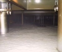
Figure 3. Unit exhibiting foaming problems.
Investigation at another large-frame gas turbine site produced the same results. This time, we had the opportunity to open the tank access doors and observed a thick layer of foam on the surface of the turbine oil. Here, we measured 117°F in the top (air zone) space, 125°F in the center (foam zone) and 135°F in the bottom (fluid zone). As the foam settled, we continued to measure the temperature of the headspace and lubricant and noticed the center zone shrank as the foam dissipated.
We confirmed these findings at many other sites. When there’s a step change in temperature at the oil level (measuring from top to bottom), foam is in the fluid. When there’s a slope change in temperature above the oil level, then there’s good certainty that foam is present in the reservoir. Some have even installed a see-through window in the tank’s access panels to confirm this foaming and watched the buildup as it happens.
We also noted that the practice of increasing the vacuum in the tank to pull out the foam doesn’t work. The increased vacuum simply increases the volume of air coming into the tank. This effectively overcomes the effects of gravity in the Stokes equation and can increase the foaming level.
Keep foam under control
Foam can be a major decomposition pathway for a lubricant, so additives are used to control it. However, like all additives, they have a limited life time. Foaming increases as the additives become less effective. The production of foam increases oxidation and varnish production. The point is that if foaming is present, varnishing won’t be far behind. Check the basics first, and use nonstandard tests to confirm the cause. Don’t assume a lack of antifoam is the reason. We suggest a back-to-basics approach for a cure.
Dave Wooton, Wooton-Consulting, Gerald L. Munson, Fluid Assets and Greg Livingstone, Fluitec International


