10 motor performance characteristics every industrial maintenance team should understand
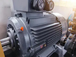
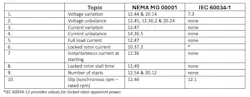
Need quick, practical ways to assess three-phase squirrel-cage motor performance on the plant floor or in the field? The following "rules of thumb" and real world examples may help. They cover 10 characteristics associated with motor starting and steady-state operation, referencing NEMA or IEC standards where applicable (Table 1).
These rules include everything from how to quickly determine acceptable operating ranges to identifying overload conditions. When applied thoughtfully, they can help you quickly spot applications that deserve a closer look or where derating or equipment changes may be needed.
1. Voltage variation
Rule: This is a variation of plus/minus 10% at rated frequency for induction motors.
Example: A 60Hz motor is rated 230 volts. The motor is used on a 208-volt system and the supply voltage at the motor is 203 volts. Is the supply voltage within the NEMA and IEC tolerances?
Evaluate using formulas: Acceptable variation from rated voltage = Rated voltage x (0.90 or 1.10)
230 x 0.90 (100 - 10 = 90%) = 207 volts
230 x 1.10 (100 + 10 = 110%) = 253 volts
The 203-volt supply voltage value is below the acceptable range of 207 to 253 volts. Thus, it is not an acceptable value. The motor may need to be derated or replaced with a motor rated 200 volts for use on a 208-volt supply. It is not uncommon for voltages at the motor to be as low as 190 volts on a 208-volt system.
2. Voltage unbalance
Rule: There is a maximum 1% voltage unbal¬ance at motor terminals without derating.
Example: A 50 hp (37 kW) motor is used on a 480-volt system and the line-to-line voltages at the motor are 451, 458 and 474 volts. Is this voltage unbalance within the NEMA tolerance?
Evaluate using formulas: Average voltage = Sum of line-to-line voltages / 3 =
(451 + 458 + 474) / 3 = 1383 / 3 = 461
Determine acceptable voltage unbalance range = Average voltage x (0.99 or 1.01)
Use absolute values for results
Deviation from average = (461 – 451) = 10
Deviation from average = (461 – 458) = 3
Deviation from average = (461 – 474) = 13
Maximum deviation from average = 13
Percent voltage unbalance = (Maximum deviation from average voltage / average voltage) x 100 =
(13/ 461) x 100 = 0.028 x 100 = 2.8%
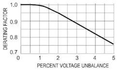
The 2.8% voltage unbalance exceeds the NEMA 1.0% limit and requires derating (see Figure 1). The derating factor for 2.8% unbalanced voltage is about 0.9, meaning that the motor should be derated to 0.9 of its nameplate rated power.
Figure 1: Medium motor derating factor due to unbalanced voltage (NEMA MG00001, Figure 14-2)
3. Current variation
Rule: There is a maximum 10% from rated current with rated voltage, frequency and at output power rating.
Example: Using the previous example 100 hp (75 kW) motor rated 115 amps at 460 volts, determine the maximum current variation.
Evaluate using formulas: Acceptable variation from rated current = Rated current x (0.90 or 1.10)
115 x 0.90 (100 - 10 = 90%) = 103.5 amps
115 x 1.10 (100 + 10 = 110%) = 126.5 amps
Note that the results are the same as for full load amps variation. (See #5.)
4. Current unbalance
Rule: At normal operating speed, the percent current unbal¬ance will be approximately 6 to 10 times the percent voltage unbalance.
Example: Use the value 2.8% voltage unbalance from the voltage unbalance example.
Evaluate using formulas:
Approximate current unbalance at six times the voltage unbalance = 6 x 2.8% = 16.8%
Approximate current unbalance at 10 times the voltage unbalance = 10 x 2.8% = 28.0%
5. Full load current
Rule: Full load current can vary ±10% from rated.
Example: A 100 hp (75 kW), 460 volt motor is rated 115 amps. At full load it is drawing 121 amps. Is it overloaded, or is the current within the NEMA tolerance?
Evaluate using formulas: Acceptable current range at full load = Rated full load amps x (0.90 or 1.10)
115 x 0.90 (100 - 10 = 90%) = 103.5 amps.
115 x 1.10 (100 + 10 = 110%) = 126.5 amps.
The 121-amp value is between the 103.5 and 126.5 amp values; thus, it is acceptable. Note though that it could indicate an overload condition since it is above the nameplate rating.
6. Locked rotor current
Rule: Use the ranges specified for the kVA code.
Example: The 100 hp (75 kW) motor in the example above has a kVA code letter G, indicating 5.6 – 6.3 kVA per horsepower. The measured locked rotor current is 777 amps. Is that value within the NEMA tolerance?
Evaluate using formulas: Locked rotor amps (LRA) = (starting kVA/hp x hp x 1000) / (volts x 1.732) (for a three-phase motor)
LRA = (5.6 x 100 x 1000) / (460 x 1.732) = 703 amps
LRA = (6.3 x 100 x 1000) / (460 x 1.732) = 791 amps
The measured 777-amp value is between 703 and 791 amps, thus it is acceptable.
7. Instantaneous current at starting
Rule: This can be 1.8-2.8 times locked rotor amps.
Example: The 100 hp (75 kW) motor in the examples above has a kVA code letter G and is tripping the circuit protection at startup. The initial momentary starting current is 1,311 amps as measured with an ammeter capable of measuring instantaneous current. Is that value within the NEMA tolerance?
Evaluate using formulas: Using the values from the previous example, the LRA should be between 703 and 791 amps.
Minimum instantaneous starting current =703 x 1.8 = 1,265 amps
Maximum instantaneous starting current =791 x 2.8 = 2,215 amps
The instantaneous current of 1,311 amps is between 1,265 and 2,215 amps; thus, it is acceptable.
8. Locked rotor stall time
Rule: The minimum capability is not less than 12 seconds for motors not exceeding 500 hp (375 kW). Exception: 2 pole Design BE motors time limit is eight seconds.
Example: A 400 hp (300 kW) 4 pole Design A motor should be able to withstand locked rotor current for not less than 12 sec¬onds. It is also required that the inertia of the load not exceed the values in MG 00001, Table 12-7.
A 200 hp (150 kW) 2 pole Design BE motor should be able to withstand locked rotor current for not less than eight seconds. It is also required that the inertia of the load not exceed the values in MG 00001, Table 12-7.
9. Number of starts
Rule: Two successive starts with motor initially at ambient; coast to rest between starts. Or, one start with motor at temperature not exceeding its rated load operating temperature. There is no power rating limit for this standard.
Example: Note that the limit for the number of starts could be applied to a 1 hp (0.75 kW) rating just the same as to a 1000 hp (750 kW) rating. However, the 1000 hp (750 kW) example motor is much more likely to have winding temperature detectors, which can be used to determine rated load operating temperature and winding temperature prior to restarting.
10. Slip (slip = synchronous rpm – rated rpm)
Rule: Slip can vary 20% from rated speed slip (slip = synchronous rpm - rpm).
Example: A 50Hz, 4 pole motor has a synchronous speed of 1500 rpm and a nameplate full load speed rating of 1475 rpm.
Evaluate using formulas: Slip rpm = synchronous speed – rated speed rpm
1500 - 1475 = 25 rpm
Acceptable slip rpm limit at full load = Slip rpm +/- 20% slip rpm
Slip rpm maximum = 25 + (20% x 25) = 25 + 5 = 30 rpm
Slip rpm minimum = 25 - (20% x 25) = 25 - 5 = 20 rpm
Acceptable speed range = synchronous speed minus minimum or maximum slip
1500 -20 = 1480 rpm
1500 - 30 = 1470 rpm
Note that any full load speed below the rated 1470 rpm could indicate an overload condition.
While not a substitute for detailed analysis, these rules of thumb provide quick, practical ways to identify three-phase motor applications in the field that may require closer review, derating or equipment changes - helping improve reliability, reduce nuisance tripping, and prevent premature motor failures.
About the Author
Tom Bishop
P.E.
Tom Bishop, P.E., is a senior technical support specialist with the Electrical Apparatus Service Association and has more than 30 years of hands-on and engineering experience at electrical machinery manufacturing and apparatus service firms. Bishop has authored dozens of technical articles and papers and presented numerous seminars on electric motor application, maintenance, and repair. Contact him at [email protected].