Why all inverter-rated motor windings are not the same
Key Highlights
- IEC and NEMA motor standards differ, requiring careful evaluation in converter-fed systems.
- Always match IVIC ratings to actual converter stress for long motor life.
- Voltage rise time and overshoot factors directly impact insulation reliability.
- When in doubt, specify IVIC C to ensure safe operation in IEC machines.
In today’s economy, maintenance personnel may source electric motors from all over the world. While this provides plenty of options, it also can result in some unexpected outcomes–especially for induction motors used with variable-frequency drives (VFDs).
Most motors rated 500 hp (373 kW) or less conform to basic manufacturing standards established by the National Electrical Manufacturing Association (NEMA) or the International Electrotechnical Commission (IEC). Both of these standards specifically define voltage stress limits for induction machine windings and insulation systems for VFD applications. But NEMA-rated inverter-duty specifications, though familiar to many, do not apply to globally sourced IEC motors.
With that in mind, this article provides a brief overview of IEC standards pertaining to voltage stress on motor windings in VFD applications. (Note: to be consistent with IEC terminology, instead of “VFD” the rest of this article will use the term “converter”.)
IEC standards for motors used with converters
According to IEC Std. 60034-1, 7.2.1.2, the requirements of IEC Std. 60034-25 apply for squirrel cage induction machines operating on static converters because the supply’s harmonic content–harmonic voltage factor (HVF)–will be greater than permissible in normal operation.
IEC Std. 60034-25 provides useful information and guidance on the application and specification of converter-duty designs and converter operation of regular IEC Std. 60034-12 electrical machines. It also explains how each drive system component affects operation and performance–from the supply system, cabling, converter and filters (if installed) to the electrical machine, mechanical shafting, grounding system, and control equipment.
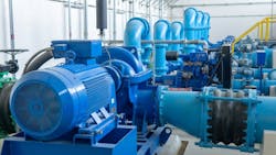
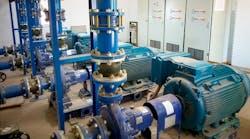
Insulation systems for IEC machines operated with static converters (see Figure 1) must be qualified either to:
- IEC Std. 60034-18-41 (Type 1), for machines rated 700 V or less where partial discharge activity is not present in normal operation (these typically will have random-wound stator coils).
Or to:
- IEC Std. 60034-18-42 (Type 2), for machines rated greater than 700 V where partial discharge activity may be present in normal operation (these typically will have formed coil windings).
Determining the IEC impulse voltage insulation class for a specific motor
Manufacturers should be able to supply the impulse voltage insulation class (IVIC “X”) for IEC motors (see IEC Std. 60034-18-41). This designation indicates the limits of impulse rise time and peak-to-peak voltage the insulation system can withstand at the motor terminals. The rate of change in the voltage impulse rise time can stress turn-to-turn insulation, whereas the peak-to-peak voltage can stress phase-to-phase or phase-to-ground insulation.
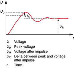
Peak voltages at the drive system output terminals are a function of the AC input voltage and the DC link voltage in the converter section. Typically, they will be 1.35 to 1.51 times the input voltage. For example, an input voltage of 480 VAC will have a potential peak of 650 to 725 VAC at the drive’s output terminals. Figure 2 shows the waveform of a Pulse Width Modulated (PWM) voltage impulse that occurs at the converter’s specified carrier frequency.
How peak voltages affect motor windings
On converter-fed machines, the peak-to-peak voltages at fundamental frequency and the PWM rate can significantly degrade phase-to-phase and ground-wall slot insulation. With turn-to-turn insulation, the impulse rise time and jump voltage (i.e., a sudden voltage spike at the start of each impulse) will have the greatest negative effects.
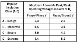
IEC Std. 60034-18-41 (Annex C) requires manufacturers to specify the limits for reliable machine performance under converter-fed conditions by listing the impulse voltage insulation class (IVIC) A, B, C or D (see Table C-1) on rating plates and in their documentation.
Table 1 provides multipliers for determining the maximum allowable voltages for 500 V insulation systems. To calculate the actual peaks, multiply 500 by those values (e.g., for IVIC A, phase/ground: 2,3 x 500 V = 1,150 V).
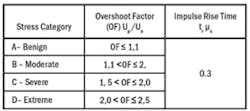
IEC Std. 60034-18-41, 7 specifies four overshoot stress categories for Type 1 insulation systems and uses a default rise time of 0.3 μs (see Table 2):
- The benign (A) level (≤1,1) relates to a converter directly coupled to the machine or through a very short cable.
- The range spanning 1,1 to 2,0 is equally split between moderate (B) and severe (C) overshoot levels, with C being recommended when the machine application is unknown.
- The extreme (D) level (>2,0 to ≤2,5) may occur with long cable lengths and when regenerative breaking can occur or in specific crane applications.
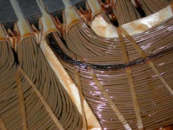
IEC Std. 60034-18-41 (Annex B) provides an example of the maximum overshoot factors for a 500V-rated winding fed from a 2-level converter. If the IVIC stress category used is less than the converter application requires, the electric machine probably will not last very long in service before a winding fault occurs–typically, a turn-to-turn short (see Figure 3).
Final thoughts
Here are some things to remember and questions to ask before selecting an electric motor with a winding rated for VFD/converter operation:
1) Not all VFD/converter-rated systems are created equal from a standards perspective; NEMA and IEC provide different guidelines.
- NEMA Std. MG 1, Part 31
- IEC Std. 60034-25
2) Ask questions about VFD/converter applications, such as:
- What is the supply voltage?
- How far from the VFD/converter will the motor be in service?
- Are there any output filters on the VFD/converter?
- Is regeneration or dynamic braking required?
Unless all application details are unknown, specify IVIC C at a minimum when procuring an IEC machine.
About the Author
Matthew Conville
Matthew Conville, MBA, PE (EEMSCO, Inc., Evansville, IN) was formerly an EASA technical support specialist. EASA, Inc. is an international trade association of more than 1,700 firms in nearly 70 countries that sell and service electromechanical apparatus. For more information, go to www.easa.com.