Beyond FISCO - a fieldbus that won't fail you when dealing with hazards
As one of the more successful communication protocols for process control and industrial automation, fieldbus has proven its merit in bringing projects on-line earlier and more efficiently, allowing advanced digital feedback and control to processing plants previously stuck in the analog age. This allowed far more exacting process control, greater autonomy of control loops, accurate trending, greater centralized monitoring, and lower installation costs through easier wiring and faster commissioning. However, when it came to the hazardous environments often encountered in many chemical, pharmaceutical, plastics and petroleum plants, fieldbus initially fell short when intrinsically safe techniques were required.
Users of intrinsically safe devices in conventional control schemes have been used to the flexibility and ease of use afforded by the Entity Concept since the late 1980s. FM in the US led the way in simplifying the process of confirming the safety of intrinsically safe loops and the Entity Concept now governs how every non-fieldbus IS loop is designed and documented.
Initially, fieldbus implementations went the same way: use a conventional IS interface, apply the industry-standard Entity Concept and the loop (now a segment) would be safe. The problem was conventional IS interfaces under the Entity Concept allowed only 80mA or so, barely enough to drive four devices at an average draw of 20mA per device. Fieldbus segments with only 4 devices somewhat defeated the point of early fieldbus justifications; plants still had lots of cable, and hardware costs went up.
Technology stepped up to the challenge in the form of FISCO (Fieldbus Intrinsically Safe Concept) which was developed in the late 1990s. Work in Germany had established that if cables and device parameters were defined by boundary values, modern electronic current-limiting designs could allow more current and still remain intrinsically safe. By taking advantage of this new technology, FISCO succeed in making more current available in hazardous locations—a full 115mA in worst-case (hydrogen) areas, enough to comfortably drive five devices, rather than the 80mA (4 devices) allowed by the Entity Concept.
Improvement, indeed. Yet FISCO makes this incremental gain at the expense of operational limitations because these units are complex pieces of electronics, generally based on switch-mode power supplies with duplicated current-limiting networks. This complex circuitry creates more heat and reduces unit reliability (complexity = more components = lower MTBF). Furthermore, a primary requirement of FISCO design is that the maximum allowable trunk and spur lengths fall from 1900m to 1000m, and from 120m to 30m, respectively. In addition, all devices and cable must be FISCO-compatible, further limiting choices in installing fieldbus networks.
For some time then, many I & C engineers have been searching for a new solution that would allow them to maximize intrinsically-safe segment capacity and operational ease within hazardous applications to the same level currently enjoyed within non-hazardous implementations.
The split architecture solution
At last, technology has come through once again with a solution. The capacity barrier of FISCO has now been significantly surpassed by a novel split architecture design that has already proven itself in the field.
Engineers at MooreHawkea division of Moore Industries-International, interface solution experts based in North Hills, Californiadeveloped this new technology by reexamining traditional approaches to pushing the capacity limits of intrinsically safe segments.
It quickly became evident that the primary cause of low segment power in fieldbus applications was the placement of the main current-limiting resistor at the point of highest current: the IS interface between the safe area and the hazardous area.
In response, MooreHawke developed a split architecture approach using a field-mounted device coupler, and an associated power supply with a safe-area interface. Here, the total resistance requirement is obtained via a split resistance; a small resistor is used in the IS interface and a larger resistor is placed in the field device coupler. The small (trunk) resistor ‘sees’ a large current (sum of all devices), but only generates a small voltage drop. The larger (spur) resistor ‘sees’ a small current (single device) and so only generates a small voltage drop.
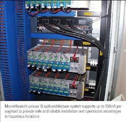
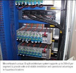
Subsequently approved by the FM (US) and SIRA (ATEX) certifying organizations, this design enables intrinsically safe fieldbus segments to support up to 350mAenough to power 16 devices at 500m while still being intrinsically safe for hydrogen at the individual spur connection. This allows fieldbus designs to be just as cost-effective and efficient in hazardous locations as it has been in non-hazardous applications.
In terms of reliability, the split-architecture power supply steps around the complexity associated with FISCO circuits by the use of a conventional wire-wound resistor which, in IS terms, is deemed to be infallible. To further augment the overall systems reliability, the MooreHawke design also incorporates full AC/DC power conversion, simple linear power supply, and full galvanic isolation, with built in redundant supplies. Here again, fewer components translate into greater reliability. MTBFs (AKA MTTF) rise.
Entity Parameters
One of the advantages claimed for FISCO systems is that if the design uses a FISCO Power Supply, FISCO-approved devices, and FISCO-marked cable within the FISCO length limitations, then the segment meets the FISCO requirements and no Entity Parameter calculations need be done—a previously laborious process employed to confirm that the inherent energy storage in any device, plus its connecting cable, were within the allowable parameters in that particular hazardous environment. FISCO removes that issue to save hundreds of man-hours, especially since no-recalculation need be performed should additional devices be added to a segment; a not uncommon event in most facilities.
At first glance, the split-architecture system, being an Entity design, seems to fall back into requiring new calculations per segment whenever additions are made. However, the unique MooreHawke design has intrinsically safe current limiting resistors per spur, making each spur an independent IS loop.
Also, IS fieldbus devices all have the same minimum Entity parameters as a requirement of their Foundation fieldbus approval. This means that while Entity calculations are indeed required, they only have to be done once. This is normally documented for the longest (worst case) spur length, 120m. After that, no device or spur can be any more "worse," so no more calculations are required. Nor does any additional device present any problem.
Considering all of the above, I & C engineers get to have the best of all worlds: 1) the digital efficiencies of fieldbus; 2) the long cable lengths, reduced documentation, and unrestricted device (non proprietary) benefits of the Entity Concept; and 3) vastly increased power (350 mA) that goes beyond FISCO to drive the maximum number of devices.
Increased flexibility during installation
Having access to the full 1900meters/120meters per spur (limited only by Ohm’s law) allows systems designers to apply the operational advantages of fieldbus to all hazardous areas of a plant, inside or out, almost as if they were looking at a non-hazardous plant. This simplifies installation when facility engineers wire their DCS system, whether retrofitting an older plant or building one up from a "greenfield."
While a collective experience is growing in fieldbus implementation, many installation contractors are still learning the process. One of the issues that frequently causes problems during installation is the fieldbus requirement to have a ‘terminator’ at each end of the segment. Operationally, these terminators prevent reflection of the high frequency communications signal and subsequent interference. However, correctly determining the right amount of terminators, and where to place them, can prove challenging, leading to a common situation of having too many or too few.
Once again, technology came up with a solution. To reduce any resultant communication errors during segment commissioning, a unique auto-terminator feature was incorporated into the MooreHawke device couplers. This design allows significant time and labor savings during installation because it helps eliminate wiring errors.
Reducing downtime and easing maintenance
The new circuits that help propel fieldbus to increased functionality also work to improve the reliability of hazardous plant operations. As it is, MooreHawke's ROUTE-MASTER system has 99.99993% availability because of the use of passive components, simple design and built-in DC power redundancy.
Further advances have also been made in the field device coupler itself, specifically in the area of spur short-circuit protectionan important consideration since a single spur fault can bring down the entire segment.
Installing a series fuse per spur is a well-proven technique and many such installations exist today. When a fuse "blows," the fault is isolated quickly, no segment-loading effects can occur, and adjacent devices are completely unaffected. Simple fuses have enormous MTBF and are generally inexpensive. On the other hand, blown fuses must be physically replaced and though this can be done with the segment on line, it can still be a maintenance nuisance.
In keeping with a theme of making fieldbus systems work for the benefit of the plant, technology managed to come up with a simple solution for spur protection when accessing a fuse proves difficult. MooreHawke, for one, offers a feature that provides spur protection via a fold-back technique which locks in a small 2 mA loadjust enough to turn on an LED lightand then removes the device from the segment. Once the short is removed, the coupler automatically resets the device on the network.
This approach is distinctly different from earlier current-limiting designs which, as the name implies, simply hold the fault current on the segment at a fixed (and always higher-than-normal) value. A fixed current of 60mA is common, and this can quickly overload power supplies and crash the segment. On the other hand, the fold-back technique completely eliminates any and all fault loads from the segment and allows the rest of the system to remain up and running.
Modern device couplers can also ease the maintenance of control systems through diagnostic capabilities in excess of what Foundation fieldbus or Profibus has to offer by themselves. Some couplers contain LED indicators to provide status checks at a glance. Built-in access points for hand-held communicators such as fieldbus trouble-shooting devices also save time.
A promise fulfilled
For plants that process chemicals, pharmaceuticals, petroleum and other products whose production may involve hazardous environments, it appears that recent technological improvements in split architecture systems design have finally delivered what FISCO promised: intrinsically-safe segment capacity virtually indistinguishable from non-hazardous fieldbus implementations.
For more information about the MooreHawke line of device couplers, distributed I/O, temperature sensors, transmitters, alarm trips and signal conditioners, contact Moore Industries-International, Inc. at 16650 Schoenborn Street, North Hills, CA 91343; telephone 1-818-894-7111 or visit www.miinet.com.

