Make sure wireless will work for you before implementation
Wireless appears to be the answer to many tough applications problems, ranging from the need to connect just one more instrument to a control system without rewiring hundreds of feet of conduit to outfitting a remote effluent monitoring station five miles away. To many, wireless is a conduit to opportunity, without the need for conduit.
But will wireless work in your application? In many cases, you can’t tell at a glance.
Those pine trees might interfere with a signal. The wireless signal might not be able to pass through that building. Your area might have too much electrical noise, excessive interference or conflicting signals.
One solution some wireless vendors offer is a detailed engineering analysis, involving coordinates, site maps, topographical maps, and so on. Another more empirical way to evaluate suitability is to take a demo system to the plant and try it out.
Surveying sites
When plant professionals ask if wireless will work in their plant, we’ve learned that blanket statements or hurried assurances are inadequate responses. Instead, you should consider doing a site survey to find out for sure.
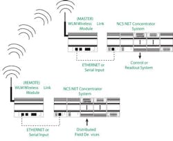
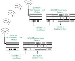
This involves mounting a transmitter and an antenna at remote sites and an antenna and receiver at the controller site in a point-to-point configuration (Figure 1). Then, fire it up and see if it works. The radio’s onboard diagnostics quantify the signal strength on each hopping frequency the radios use to transmit data. This also helps to determine if any portion of the spectrum is subject to interference from co-located radio systems or cell towers. If so, the final wireless system can be programmed to ignore the “noisy” portions of the spectrum.
Figure 1: A simple point-to-point demo system gathers data at a remote site and transmits it to a receiving system in the control room.
A steel mill, for example, had been using a manual system to collect flow meter data. Essentially, an employee toted a clipboard during routine visits to eight flow transmitter locations. The mill asked if a wireless system could reduce this labor and was pleased to learn that an omnidirectional antenna could transmit to and receive signals from the eight flow transmitter locations.
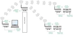
With the concept proven, the plant installed a wireless link module for an Ethernet network radio system and an Ethernet interface module with control software that enabled the distributed control system to do the flow totalization at each flow transmitter. A wireless link module in the computer room on the process floor set up in a point-to-multipoint configuration served as a multipoint master that received data from eight transmitters (Figure 2).
Figure 2: A point-to-multipoint configuration allows a system in the control room to receive data from multiple transmitters. (click to enlarge)
This hardware combination provided a reliable and versatile alternative to the mill’s inefficient use of labor. At the same time, the system provides continuous access to the process data.
Solving problems
There are always issues with signal transmission in an industrial environment. A chemical plant, for example, had a signal transmission problem at a remote weather station. The plant’s weather station used a telephone line and modem to transmit wind speed, wind direction, temperature and humidity to a local Modbus RTU data logger located in a building approximately 1.5 miles away from the control room.
Ants attacking the phone line caused regular signal disruptions. Also, the weather station was located in a stand of pine trees. A pretty view, but pine needles attenuate and sometimes absorb 2,400 MHz signals. A demonstration test was in order. Connecting the weather station’s data logger to a 900 MHz WLM (wireless link module) radio from Moore Industries produced a clear signal. A Yagi directional antenna on the weather station’s 30-ft. boom transmitted data to an omni-directional antenna and master wireless link module located atop the control room. The plant now receives reliable, uninterrupted weather information from the weather station.
After seeing the wireless demonstration’s performance at a site survey, some plants want additional surveys at other locations. Fortunately, a wireless demo is simple to perform. Such was the case with the chemical plant. The first location was a remote sanitary lift station. A wireless link module radio with a Modbus interface module and an analog input module converted four analog signals to Modbus RTU and transmitted them to the control room. A wireless link module in the control room sent the Modbus signal to the control system.
Initially, the second application appeared to be an unlikely candidate for a wireless system. The plant wanted to transmit data from an effluent monitoring station back to the same control room. The distance was less than one mile, but the direct line of sight was through a building housing a four-story boiler rack. An onsite demonstration proved that a wireless signal could pass through the boiler rack. Surprisingly enough, the radio’s diagnostics showed that enough signal was ricocheting through and around the boiler building to produce a strong, repeatable signal.
Again, a wireless link module radio, analog input module and Modbus interface module at the effluent station communicated through a Yagi antenna on an existing outdoor pole. To date, the control room wireless link module has been successfully transmitting clean RF Modbus RTU signals to the DCS for more than two years without a hiccup.
Using a demo system to prove that a full-scale wireless system can work saves time and engineering. We’ve duct-taped antennas to the top of a building, stood on the roof pointing an antenna manually, and used Moore Industries’s demo kit indoors and outdoors, in chemical plants and steel mills. If you want to try it yourself, ask a wireless vendor to bring a demo rig to your plant. Seeing it work is far more reassuring than any engineering analysis that only says it might work.
Shannon Erickson is an application engineer at MacGuire and Crawford, Inc., Charlotte, N.C. Contact her at [email protected] and (843) 629-0063.


