Build a centralized lubrication system
Many types of centralized lubrication systems are available to maximize equipment life and efficiency. The system choices apply to industrial equipment, steel processing, mobile equipment, pulp and paper, food and beverage, and many others.
In order to use a centralized system, a series of decisions will lead to the best results for the application. The following is a collection of issues that I have encountered over the last 40 years. Many struggles and equipment failures with their associated downtime could have been greatly reduced by following these proven methods, and hopefully, these tips will help you avoid some common pitfalls.
The first decision is which lubricant type to use: oil or grease. Using grease will disqualify an orifice type of system. When using grease, the base oil’s viscosity along with the grease consistency and NLGI (National Lubricating Grease Institute) rating will guide you to the next system selection. Thicker grease products such as those with NLGI #2 ratings (with a consistency like peanut butter) may require systems with higher pressure capabilities like series progressive, single-line parallel, or dual-line systems. In comparison, greases rated NLGI 000 have a consistency similar to olive oil. In either case, the person selecting between oil or grease needs to ensure the viscosity of the oil and the base oil within the grease can adequately sustain the load and speed of the application. Obtaining the original equipment manufacturer’s recommended lubricant specifications is commonly suggested.
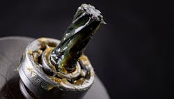
How well the lubricant is handled, whether oil or grease, will also determine a successful outcome. Too many systems fail to deliver lubricant only because a contaminated lubricant (see Figure 1) has caused system component failure. While system failures are often blamed on the components, contaminated lubricant is the main cause of failure, just like in any fluid power system. Much of the contamination enters the product through handling or transfer. Transfer pumps with filtration should be used when dispensing oil from its original containers. It is important to remember that even new oil can have particulate levels higher than the ISO cleanliness codes of most components.
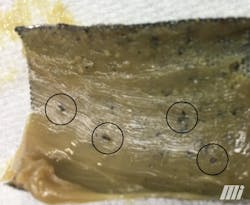
Figure 1. Dirt within the grease is shown caught in a strainer. (Photo: Motion.)
Some examples of how contaminants are introduced into lubricants include:
- removing grease pumps from empty containers and laying them on the floor while exchanging a new container
- exposing lubricant containers to weather or dusty environments
- refilling smaller drums (re-packaging for convenience) from larger containers (Figure 2).
I often observe lubricant drums with water overflowing the drum cover, or the lid rusted from previous water exposure. Usually, the contaminant is introduced into the system when filling reservoirs or prefilling the system. Open ports on components, hoses, tubing, and fittings during handling while installing is an invitation for dirt to enter the completed system. Take proper care when handling any lubricant, for the health of the system and the lubrication point. Why lubricate a rolling element-type bearing with contaminated product?
Figure 2. This keg was refilled multiple times, introducing dirt. (Photo: Motion.)
Oil as a lubricant
Let’s say that after doing your homework to determine the lubricant requirements, you concluded that oil should be used. The next step is to decide if the system will recover and recirculate the oil or if it will be a terminating style, also known as a “lost oil” system. The term lost oil means the oil is delivered to the lubrication point and not reclaimed. Recirculation systems offer a much cleaner machine environment but can be more challenging in design and installation. The recirculated oil needs to be captured and returned to the main reservoir.
Filtration is important to protect the pump since contaminants will be washed back into the return lines. However, there is a delicate balance between providing suction line filtration and cavitating (starving) the pump. Pressure line filtration after the pump outlet is needed to protect the components that measure and dispense the lubricant. Filter element selection criteria for a return line filter must also allow for sufficient flow (gravity) back into the lubricant reservoir and not cause a backup in the gravity return lines, which would create an environmental mess and may starve the pump’s inlet. Be aware that cool ambient temperatures may impact viscosity and slow the return flow through the return line filter element. Oil temperatures will lower during extended periods of shutdown, such as over a weekend, resulting in operational issues during restarting if the viscosity variance was not accounted for in the design process. Pressure side filtration can accommodate lower-micron-rated elements, but pressure drop values based on viscosity, temperature, and flow rate need to be reviewed. Terminating oil systems (lost oil that does not collect dispensed lubricant) do not have to contend with return-line problems but can create a cleanliness issue in and around the equipment.
Grease as a lubricant
If a grease product is needed, filtration becomes more difficult. Because grease contains a thickener, a strainer should be used with a 40- to 60-mesh size. A 100-mesh strainer can occasionally be used, only after consulting the grease supplier or manufacturer. Mesh elements that are too restrictive can separate the thickener from the base oil. The thickener will appear as a wax-like substance in the clogged element.
The remaining oil without the thickener may proceed past the plugged element to the lubrication point but will not be adequately retained; instead, it will drain out of the point. In any case, a heavy-duty element must be used, so it does not collapse during high-pressure differential caused by element blockages. Collapsed elements not only allow non-filtered product to pass, but the particles trapped by the failed element also flow downstream, along with materials of that element. Generally, the grease supplier or manufacturer should be consulted to ensure the product can be used under pressure in a centralized lubrication system. Grease separation is often observed in system components, causing system failures.
Solid additives within lubricants
Lubricants containing solid additives may benefit the lubrication point but can harm the lubrication components, including the pumping system. Most lubrication equipment suppliers state a maximum percentage of solid lubricants that are allowed. The solid particles can deposit within lubrication system components, causing them to lock up. If you have questions about whether the lubricant will cause a system issue, consult the lubrication equipment supplier. Also, the lubricant in a simulated system can be tested to prove the system’s ability to perform correctly.
Equipment protection
Whether the monitoring is performed on-site or remotely through Wi-Fi or Bluetooth, several levels of protection ensure that you get feedback should something go wrong in the system. Feedback can be as simple as a lubricant level indicator for the reservoir. A more complex system will confirm a completed lubrication cycle or signal that a blockage has occurred. Broken line detection will monitor the hoses that are regularly flexing. Temperature monitoring of a lube point can also be included as added insurance. When thinking about using feedback and to what extent, consider the potential cost of a component failure and the associated downtime. It is not uncommon for total repair costs—including lost production—to exceed $100,000 just because a hose failed that fed a critical bearing, and there was no method used to detect the failure.
System styles
After the above specifications are determined, select a product type. If you have a limited budget, an orifice system (single-line resistive) may fill the need, but remember, this type provides the least protection. Injectors deliver oil or grease under pressure and permit individual volume adjustments per point, with visual indicators showing meter movement.
The system that provides the most flexibility when providing feedback is the series progressive. This diverse, widely available product meters oil or grease and easily provides feedback of a blocked lube point through the sequential movement of the metering pistons. Series progressive systems also can confirm the completion of lubrication cycle(s), pump failure, and more.
Dual-line systems are often used in small through extended systems because of the lower pressure drops within the piping network. They can provide visual or electric feedback of valve movement. Mist systems are available and can be a good choice, if maintained properly to prevent excessive mist from entering the atmosphere. Air-oil lubrication systems have become an alternative to mist systems and even grease systems. Pump-to-point lubricator boxes for using oil are also available. Single-point lubrication products can now provide a good alternative to the installation costs of traditional systems, with newer products capable of remote mounting and Bluetooth connectivity.
Fluid connector choices
Fluid conveyance products used for installation also affect the outcome of the overall system. Tubing, hose, fittings, and pressure gauges must be chosen to exceed the pump’s pressure capabilities. Tubing inner diameters must allow for sufficient flow with low pressure drop, especially when grease is the lubricant. The tubing inner diameter, the NLGI rating and the lowest ambient temperature will be the determining factors of how far your pump can be placed from the system. A thicker wall tubing will provide a higher maximum operating pressure but can restrict flow. Hose inner diameters, if too large, can now contribute to an accumulator effect (compression of the product), rendering some monitoring capabilities ineffective. Hoses in moderate- to high-pressure systems must be reinforced with braid to prevent hose expansion. Push-to-connect fittings are great for helping speed installation but, in some cases, may not meet the pressure rating of the system. Fittings need to meet and preferably exceed the ratings of the connecting product.
Installation guidelines
All the proper choices previously discussed will diminish results if the products are not installed with success in mind. Correct orientation can be critical for pumps and distribution valves. Try to place items such as injectors, series progressive valves, and dual-line blocks as central and close to the lube points as possible. Some valve styles may require flat mounting surfaces so the block can be torqued evenly to the surface, which will not restrict internal movement.
Protect from heat using shields, such as a fire sleeve placed over conveyance lines. Mounting away from or under the heat source will also protect lubrication components and lubricant in the lines.
Pre-filling all lines with the recommended lubricant is critical to ensure that lubrication points start receiving product as quickly as possible. Lubrication systems are not meant to fill lines—they are intended to replace lost lubricant at these points in small amounts. It could be significantly time-consuming to rely on the system to fill all the lube lines.
Standard wiring practices should be adhered to, such as isolating signal wires from high-voltage lines, so electrical noise is not introduced. Ground controllers correctly and ensure there is no floating ground potential to cause controller failures.
For additional support, it is an option to engage in-house technicians/engineers or a third-party lubrication specialist in preparing the best solution for your facility. Considering the tips provided here will be the first step to the right path.
This story originally appeared in the August 2022 issue of Plant Services. Subscribe to Plant Services here.
Denis Balogh, business development manager at Mi Fluid Power Solutions, has been involved in centralized lubrication and fluid power systems since 1978, working for manufacturers and industrial distributors. He has provided solutions to lubrication-related issues in most industrial markets and has been heavily involved in the primary metals industry. Balogh is a member of the Association for Iron and Steel Technology (AIST) and is part of its Lubrication and Hydraulics Technology Committee. He is participating in revising its Lubrication Engineers Manual and previously contributed to the manual’s second edition.