Select the correct blower technology for industrial wastewater treatment applications
Blower selection is an important decision when designing a new wastewater treatment plant or upgrading existing facilities. The proper selection of blower equipment for the application, as well as purchasing from a reputable supplier, can save thousands of dollars in energy, repairs and maintenance costs. This article provides an overview of the blower technologies available for wastewater treatment, and discusses the advantages and limitations of each technology in various wastewater treatment applications.
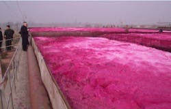
Take a look at a municipal wastewater treatment plant near a textile factory in Asia (Figure 1). Is there any question as to why we treat industrial wastewater? The use of blowers for aeration and mixing accounts for 40 to 75 percent of the total energy consumption in a wastewater treatment plant. For this reason, the specification of the correct technology and size for each blower application is of paramount importance.
There are four stages of wastewater treatment:
- Pretreatment typically involves some type of filtration or screening.
- Primary treatment can be accomplished by either dissolved air flotation (DAF) or sedimentation.
- Secondary treatment is most commonly accomplished by the activated sludge process, and this article covers several other methods of secondary treatment in addition to the activated sludge process.
- Tertiary treatment is not always required, but can be accomplished by additional filtration, advanced oxidation, UV disinfection or a combination of these methods depending on the quality of effluent required.
This article focuses on secondary wastewater treatment methods that utilize blowers in their processes.
Secondary wastewater treatment applications
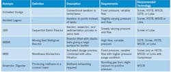
The most commonly used secondary treatment processes include the activated sludge process, aerated lagoon, membrane bioreactor, moving bed biofilm reactor, sequential batch reactor, and anaerobic digestion.
The Activated Sludge Process. Developed in the United Kingdom in the early 1900s and currently utilized in medium- to large-scale industrial plants, the activated sludge process separates the flocculants (i.e., suspended solids) from the wastewater through sedimentation. Effluent enters the aeration tank or lane, and low pressure air is introduced through a grid of diffusers. Water usually passes through the process in a few hours, while the sludge retention rates vary from a few days in warmer climates, to a few weeks in colder weather.
Lagoon Aeration. Similar to the activated sludge process, lagoon aeration is typically used in rural areas with small- to large-sized plants. A series of shallow earthen basins (lagoons) act as the aeration basins and holding tanks. Although lagoons are often equipped with surface aerators, there are several diffuser systems available specifically for these applications. A well-designed diffused air system uses approximately half as much energy as surface aeration.
Membrane Bioreactor (MBR). The MBR process uses additional filtration to produce a higher quality effluent and is a variation of the activated sludge process. Common in medium- to large-scale plants, the MBR features an ultrafine membrane filter installed at the discharge end of a standard aeration basin. Pumps installed on the membrane filters create a slight vacuum and pull the effluent through the membrane. The ultrafine holes in the membrane do not allow the biological microbes to pass through the membrane, keeping the microbes in the aeration basin. The membrane becomes clogged or fouled in this process and requires more frequent cleaning.
Moving Bed Biofilm Reactor (MBBR). The MBBR is a much more compact method of wastewater treatment that can be scaled to fit any size plant. In this method, the reactor is filled with thousands of biofilm carriers (plastic balls) that protect the bacteria used to breakdown pollutants in the wastewater. A diffuser grid produces the air required to effectively disperse the biofilm carriers throughout the basin, while also providing the necessary aeration for biofilm growth.
Sequencing Batch Reactor (SBR). The sequencing batch reactor (SBR) is also a very compact process typically used in small- to medium-sized plants. A small SBR consists of two equal-sized tanks that alternate between treatment stages. The process begins with the filling of one of the tanks; the wastewater is then mixed during the anaerobic stage using a jet aerator or mechanical pump. During the aerobic stage, the wastewater is aerated using a diffused air system. Next, the wastewater is allowed to settle so that the sludge can be separated from the effluent during the sedimentation stage. Finally, the effluent is drained in the decanting stage and the reactor is in idle. The idle stage can be used to perform cleaning or remove excess sludge from the reactor. As soon as the first tank is filled, wastewater is diverted to the second tank and the process begins again. The multiple tank (reactor) design allows the plant to operate continuously and larger plants use more reactors to accommodate higher loads.
Anaerobic Digestion. Anaerobic digestion is used to treat the sludge created by the wastewater treatment process, as well as other biological waste. By definition, anaerobic digestion does not use air; instead, a series of microorganisms break down solid waste into methane and carbon dioxide gas, in addition to nitrogen, ammonia, and hydrogen sulfide in smaller quantities. This biogas is extracted from the reactor and either flared to reduce greenhouse gas emmissions, or treated in a series of filters before being injected into a generator. Once injected into a generator, the biogas can be used for on-site electricity and heat generation, also known as a cogeneration system. Depending on the composition and amount of waste in the digester, this process can produce a substaintial amount of energy that can be used for plant operations.
Defining air demand
The first step in selecting blowers for wastewater treatment is to determine the air demand. The two most critical components of air demand are pressure and air flow. For most applications, pressure is defined as hydraulic head plus friction losses. For water and wastewater, hydraulic head is approximated as 0.434 PSI / FT of water depth. Friction losses are determined by the size, roughness and number of elbows and tees in the piping plus the pressure loss of the diffuser membranes or aeration nozzles.
Air flow is typically much more difficult to calculate, especially for aeration processes. The goal of aeration is to provide oxygen to satisfy biochemical oxygen demand (BOD). The dissolved oxygen (DO) level is often monitored on a continual basis to ensure proper aeration of the tank, basin or lagoon. If the BOD is not satisfied, the bacteria responsible for breaking down organic pollutants in the wastewater may die. If the bacteria die, the wastewater will no longer be treated and a low quality effluent will be released into the environment, potentially resulting in fines from local and/or federal regulatory bodies.
To avoid these complications, several design parameters must be taken into consideration including standard oxygen transfer effficiency (SOTE), standard oxygen rate (SOR), water temperature, site elevation, diffuser type (bubble size), and fouling factor. Due to the number of variables involved in calculating air flow demand, an engineering firm is often tasked with performing these calculations and assisting with equipment selection.
Blower technologies
Once the air demand has been calculated, evaluation of blower technologies can begin. Blower selection depends on the application and the air demand. Several technologies are available for wastewater aeration and mixing.
Positive Displacement (PD) Technologies. The positive displacement (PD) blower is an American invention pioneered by the Roots brothers in the late 1850s. PD machines operate with flow and pressure as independent variables. At constant speed and if pressure increases, the flow rate is largely uneffected. The efficiency curve, or specific energy ratio (SER), of PD machines is typically close to linear. This means that the efficiency of the machine is similar across the operating range which makes PD blowers the ideal choice for applications that require large variations in flow or pressure. There are two main types of positive displacement blowers:
Roots, Lobe-Style Blower –The “Roots” or lobe-style blower that was invented in the 1800s remains very much unchanged today; the primary advancement in lobe technology over the past 150 years has not been improved efficiency, but reduced noise. Bi-lobe blowers produce very high amplitude waves at a low frequency; to reduce the amplitude and increase the frequency of the waves, a third lobe was added. While this innovation decreased efficiency slightly, it reduced noise levels to below 85 dBA as mandated by OSHA. Figure 2 below shows the four stages of compression of a tri-lobe blower.
Rotary Screw Blower – In an effort to increase efficiency of positive displacement blower technology, the rotary screw blower was introduced to the market in 2009. The rotary screw blower uses a helical screw profile instead of lobes to create internal compression of the inlet air. The screw rotor profile serves a dual purpose. First, the internal compression of air reduces energy consumption by 30 percent compared to traditional lobe blowers. Second, by eliminating the pulses caused by lobe technology, screw blower noise levels are typically below 75 dBA which is three to five times quieter than conventional tri-lobe blowers. Figure 3 illustrates the compression stages of a rotary screw blower.
Rotary screw blowers can reach higher pressures than lobe blowers and often have lower operating temperatures due to the reduced slip of the rotor profile. As a result of lower operating temperature, variable speed screw blowers usually have a much wider operating range (more turndown) than lobe blowers. However, lobe blowers come in a wide variety of sizes so higher flow rates can usually be achieved with a lobe blower than a rotary screw blower.
Centrifugal technologies
Centrifugal machines operate with pressure and flow rate as dependent variables. At constant speed and if the pressure increases, the flow rate will decrease. The efficiency of centrifugal machines is much better than positive displacement machines at a given design point. However, the specific energy ratio (SER) curve of a centrifugal machine is parabolic; as the operating conditions deviate from the design point, the efficiency of the machine decreases. Therefore, centrifugal blowers operate best as base load machines or in applications with constant pressure.
The first working centrifugal compressor was produced around the turn of the 20th century as a type of gas turbine. Currently three different designs of the modern centrifugal blower are in common use:
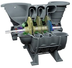
Multistage Centrifugal Blower (MSCB) – The multistage centrifugal blower (MSCB) is usually coupled directly with an induction motor driveshaft. As a result, the MSCB has the slowest operating speed of the three designs discussed in this article. The design principles for the MSCB are fairly simple: for more flow, increase the impeller diameter; for more pressure, increase the number of impellers (stages). Like all centrifugal machines, the impeller configuration has a large effect on the performance of a MSCB. A MSCB can have two to 11 stages and any number of impeller geometries to create the desired flow and pressure curve (see Figure 4).
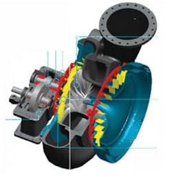
Integrally Geared Turbo Blower (IGTB) – The IGTB is driven by an induction motor via a speed-increasing gearbox. Although the motor rotates at only 1,800 or 3,600 RPM, the blower impeller rotates as fast as 30,000 RPM to produce the desired flow and pressure. The IGTB uses inlet guide vanes and variable diffuser vanes to control the air flow and pressure (see Figure 5).
High Speed Turbo Blower (HSTB) – There are two types of direct drive HSTB bearing technologies: airfoil and magnetic. Airfoil bearing HSTB were introduced to the U.S. wastewater treatment market around 2007. Unfortunately, the technology was misapplied in many applications which led to headaches for both manufacturers and consumers. It is important to know that there are installations of airfoil bearing HSTB that have great reliability, thanks to well-applied technology and a clean working environment.
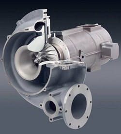
Magnetic bearing HSTB have been used in the wastewater treatment industry longer than the airfoil design. Over the years, magnetic bearing turbo has proven extremely reliable due to the magnetic bearing controller that often prevents catastrophic failure (see Figure 6). Both the airfoil and magnetic bearing machines use high speed permananet magnet motors controlled by variable frequency drives that allow the impellers to turn up to 60,000 RPM to create the desired air flow and pressure.
Of the three centrifugal technologies, the MSCB offers the most versatility in wastewater treatment due to its ability to convey digester gas as well as air. The MSCB also offers the widest flow range due to the numerous configurations available. The IGTB offers the largest flow rates and, thus, is not suitable for use in small plants. Finally, the HSTB offers the greatest potential in industrial wastewater applications due to its small footprint, high efficiency, and integrated control system.
Designing the blower system
The most important factors in selecting a blower are reliability, efficiency, maintenance and capital cost. Table 1, below, is a guide to evaluating each technology based on the four key factors listed above. Although some customers may value one factor over another, in general, the blower with the lowest overall score will have the lowest life cycle cost. It is important to remember that there is no “coverall” technology for wastewater treatment blowers. Each blower has advantages and disadvantages and should be selected based on the end user’s preference of these four factors.
Table 2 lists each secondary wastewater treatment application, its air requirements and the recommended blower technologies for that application.
Several regulatory bodies govern the compressed air industry, the most reliable of which are ISO, CAGI and ASME. It is prudent to purchase a blower from a manufacturer that is ISO 9001 certified for quality assurance. Also, request blower test certificates according to ISO 1217 (for positive displacement machines), ASME PTC 10 (for centrifugal machines), or the soon-to-be-released ASME PTC 13 (covering all blower technologies). These test procedures will ensure that the blowers produce the correct amount of air while using the advertised amount of power.
Consider the manufacturer’s service network before purchasing. Some manufacturers only have one U.S. location with a limited number of trained technicians, while other manufacturers have hundreds of technicians scattered across the country.
