The pulse of dust collectors

Many production facilities have a significant number of dust collectors. Many have continuing problems with short bag life and low-pressure problems at the farthest points from the central air system. They often run on timers. When they try to run on demand control, they often get extreme short cycling, which causes even more bag problems. On at least half of the dust collectors, most have gauges at the entry; some of the gauges are even operational. Often, the compressed air feed lines are the same size as the connector opening.
Proper operation of dust collectors is critical to minimizing cost and maximizing system effectiveness. There are many types, and sizes and many use a pulse of compressed air to clear the bag or filter. The pulse is usually controlled by a timer which might have an auxiliary demand control. The timers are generally set by the operators to what they believe is appropriate for proper cake removal and bag life.
Pulse jet dust collector
In a pulse jet dust collector, the dust is collected on the bag or fingers, and, when the cake of dust is of appropriate thickness and structure, a pulse or pulses of compressed air hit or shock the bag and knock the cake off. This pulse may sometimes be accompanied by physical shaking and even reverse air flows, depending on design.
When the cake is removed correctly from the dust collector, the system removes dust from its assigned environment and has a normal bag life. When the cake is not removed efficiently, the dust collector doesn’t remove dust effectively from its assigned environment and the bag life can be significantly shortened.
Dust collection system designs specify the compressed air inlet pressure to the manifold and pulse valves necessary for effective dust removal. The pulse valve sends a given volume or weight of air to the bag at a predetermined velocity to strike and clear the cake. The actual amount of weight of air is dependent upon the pulse nozzle being fed compressed air at a predetermined and steady pressure. The dust collector must receive the correct pressure, or close to it, and a steady repeatable pressure level for each pulse, particularly if timers are used to control the pulses. The operator may experiment to find the right timing sequence at a desired compressed air inlet pressure. However, if this pressure varies, then performance will not be consistent or satisfactory.
Installation considerations for proper compressed air supply
Short bag life usually comes from the pulsers hitting the bag when the cake is not ready to flake off or the cake has gone too long between pulsing and grown too thick and heavy to clean effectively. This causes not only short bag life, but very poor performance. There are usually several basic causes for this.
- Incorrect timer settings for the operating conditions. The actual requirement for the optimum timer setting may well change as various product runs change or even seasonally. These settings have to be set carefully to begin with and have to be monitored regularly.
- Lack of sufficient storage or compressed air supply near the inlet manifold to supply the required pulse air without collapsing the inlet pressure. With too low of an inlet pressure, the mass weight of the air pulse is too low, which then becomes ineffective in removing the cake.
- Too small of a feed line to the dust collector entry. This will have the same effect as lack of air supply.
- Too small or an incorrect regulator. This will make it unable to handle the required rate of flow required by the dust collectors.
Pulse jet dust collector operation
Improper compressed air delivery and supply may create an ineffective pulse.
- Use proper line size to handle rate of flow without high pressure loss.
- Use of storage to supply air without pulling down feed to receiver/collector.
- Monitor inlet pressure and drop at pulse.
- Monitor flow.
One very common installation or system situation causes restricted air flow. They occur because, prior to the installation or prior to some operational change, the proper rate of flow wasn’t identified for the dust collector cleaning action. Feed line sizing, regulator sizing, and air supply all require an identified rate of flow. You can’t use average flow rate.
Rate of flow
Flow rate is the average flow of compressed air in ft3/min either required by a process or delivered to the system. Rate of flow is the actual rate of flow of compressed air demand expressed in ft3/min, regardless of duration. Even relatively small air demands in ft3 can have a very high rate of flow, if they occur over a very short time period. Dust collectors have this characteristic.
Sequence controllers can have a very significant impact on the required rate of flow. For example, pictured below is a dust collector system which has six pulsing valves that use 3.5 ft3 over a half-second for each pulse. When this is a problem, appropriate storage and piping can be a very effective correction when properly implemented (Table 1 and Table 2).
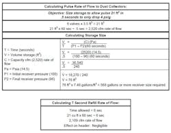
Table 1.

Table2.
The impact of two different rates of flow would show similar differences in regulator sizing if they are used on the feed line flow. The high flow velocities entering the manifold and controls for the pulse valves will create extra pressure loss through the nozzle, affecting the performance of the pulse cleaner. The same effect would show up in air receiver sizing to minimize system and feed line pressure drop if that is a question (Figure 1).
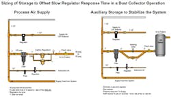
Figure 1. This is an example of utilizing storage.
Additional installation guidelines
We recommend that every feed line has a quality pressure gauge installed near the dust collector entry. Observe the pressure gauge when the pulser hits. If the pressure drop is too high (more than 10-20 psig), start looking for the cause. Record the specifications on the dust collector (cfm per pulse, feed line pressure, time per pulse, cycle time between pulses). Calculate the rate of flow, and check line size and storage. If additional storage is required, it can be calculated by using the previous formula.
The sequence and pulse jet nozzle size depends on the number of bags, type of bags, length of the bags, and the materials begin trapped. These will vary by make and model. Some rules of thumb that often apply:
- 1/2-second is commonly used for the pulse duration.
- Air flow per pulse jet is very often from 3.5 to 10 ft3
- Dust collector capacity is often increased first by lengthening the bags and/or increasing the number of bags in the housing.
- As the bag length increases, the pulse jet air demand increases. In one example, increasing from 18 in. length bags to 84 in. length bags increases the pulse demand about 25% incrementally.
- As the number of bags of the same design increase, the pulse air required increases about the same percentage.
The number of pulse jets, sequence, and air demand is needed to install any dust collector correctly to ensure an adequate flow of compressed air at the proper pressure.
With the variety of filters of modern high performance materials available, many operations are modifying their older dust collectors; however, too often the effect on the compressed air requirements is not considered.
Pulse jet dust collectors are a continuing source of leaks, particularly when pulse jet diaphragms fail, which can become a very large compressed air leak. An open ¾ in. diaphragm pulse valve can leak up to 200-250 cfm, 50 to 60-hp worth of compressed air = about $24,000/year.
Often, these are hard to hear and sometimes, when first heard, are ignored, hoping someone else will notice and repair it. After all, it is a hot, or cold, dusty, noisy job, often above ground.
There are some excellent electronic monitoring systems available that will identify leaks from failed solenoid pulse jet valves. These can also monitor filter performance and condition and monitor the system’s capability to stay in compliance.
For these systems to perform as designed, the compressed air supply should deliver solid, consistent performance at the point of use.
Note that a paddle switch visual alarm can easily be installed on the air supply pipeline. Whenever the paddle sensor sees compressed air flow, the light turns on (Figure 2).
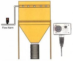
Figure 2. When the sensor detects compressed air flow, the light turns on.
When the pulse jet hits, the light turns on and then turns off when it closes. If the light stays on, there is continuous flow — a leak.
Remote gauge reading
Items such as the Cypress remote gauge reader can be mounted on critical pressure gauges in hot, dirty, hard-to-reach to places. They record the local gauge reading, digitize it, and send the information electronically through a collector to a control monitoring point where performance can more easily be continually or routinely monitored.
Automatic pressure differential pulse controllers
Automatic pressure differential pulse controllers are very effective in optimizing compressed air usage and are always recommended; however, the storage and piping has to be correct for proper operation. When not installed properly the negative impact may be significant. A chart of typical compressed air use indicates estimated compressed air savings based on valve size — a 10-row pulse jet dust collector between pressure differential control and times control set at 356 pulses/hour (Figure 3).
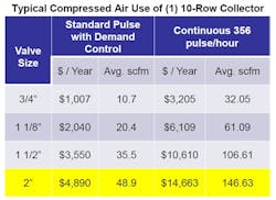
Figure 3. Compressed air savings can be based on valve size. (Source: FilterSense)
Once you are sure the installation is correct, running from a demand-side controller is always suggested. This senses the filter condition and only pulses the bag at the right time. There are some excellent electronic control systems available that can be very economical and will usually improve bag life and reduce air usage.
Summary
When a plant or operation with significant dust collecting is audited, it’s very rare to find anyone in operations who is aware of what the dust collectors’ operating specifications are and how or why the pipe sizes were selected. When you get the facts and go by the book, an amazing thing happens — they work like they are supposed to.
Dust collector troubleshooting and maintenance tips
All dust collectors need routine maintenance of clearing plugged tubes in addition to:
- continuous diaphragm/valve repair
- cleaning and checking magnehelic gauges and other critical sensors
- reset timers, if required.
When pulse valve diaphragms become worn and do not seal, filter cleaning becomes ineffective, and often the operators adjust the timers to a more frequent cycle, which offsets the lack of performance.
Generally speaking, all diaphragms should be replaced within three to five years. Ideally, when replacing one, replace them all. Obviously different operating conditions and controls will yield varying results.

Proper operating valves and diaphragms will allow better filter cleaning, reduce particle emission, and use less compressed air.
- A ¾-in. ASCO type pulse valve diaphragm kit retails for approximately $20-$25 each.
- A ¾-in. pulse valve leak may well be as high as 200 cfm. 1-1/2-in. and 2-in. valves can or do leak up to 1,000 cfm.
- Monitor all control sensors — DeltaP pressures, time delays, cycle times and cleaning times — per manufacturer specifications.
- Pulse cleaning never stops when it should (check if the pressure tubing is disconnected; check electrical connections; and check high and low pressure points).
Diaphragm and valve maintenance is often overlooked in many plants until they grow to the magnitude where there’s not enough air to feed the hungry leaks, at which time a crisis arises, possibly leading to the purchase of additional compressed air. It’s obvious that poorly operating, and even more so leaking, valves and diaphragms can use significant volumes of very expensive compressed air. It behooves any plant that operates pulse jet dust collectors to know them well and maintain them properly.
Current application
The dust collector feeds are/are not generally well sized, and each does/does not have an air receiver or adequate effective storage between it and the collector. Observation of the operation and discussions with plant personnel indicate the demand controls are/are not working well and the bags sloughing off properly. All units are/are not running on timers. There does/does not appear to be a problem of pulling low pressure in surrounding lines and also low pressure to the collector. There are/are not enough appropriately installed gauges to observe the operation at the time of the audit.
When the feeds and installation are operating properly, the dust collector air usage will operate with less overall demand and better performance with a demand controller. The demand controller, when used without proper compressed air feed conditions, may use more air and decrease bag life and performance.
Recommended Project (#22): Modify the dust collectors by adding receiver capacity, reducing flow restrictions, and providing several indicator lights. These indicators could include a warning light with a pressure differential switch to indicate increased flow when maintenance is quickly required, a pulsed light during normal operation, and a steady light when a leak is present.
| Total cfm saved | _____ cfm |
| Recoverable savings from air flow reduction [Section 2.3] | $_____ /cfm yr |
| Total annual electrical energy savings | $_____ /yr |
| Total project cost | $_____ |
Note to Auditor: This section will have to be modified or rewritten to fit the local situation.

Phase 2 Recommendation: After the system is stabilized and reconfigured, review each dust collector operation to ensure proper bag sloughing, working demand controls, and there being no negative effects on adjacent equipment.