Storage volume for air compressors

Storage volume must be installed directly between a reciprocating compressor and the connected rotary screw and centrifugal compressors to prevent the reciprocating compressor’s pulsations from damaging the other units. Receivers sized at 1 gal per cfm should be satisfactory for this purpose.
However, the primary reason to install usable storage is to prevent short cycling from damaging a partly loaded or trim compressor. Generally, lubricated rotary screw compressor manufacturers require a minimum 90 sec cycle time, while centrifugal compressor manufacturers prefer a 120 sec cycle time. Cycle time is the interval between successive times a compressor loads. Assuming a 10-psi control band, the volume required, in gal, to achieve a 90 sec or 120 sec cycle time is equal to 4.13 or 5.5 times the cfm of the largest trim compressor, respectively. These volumes assume that the compressor is 50% loaded, which is when the shortest cycles occur.
[pullquote]The motor starter and compressor type, along with control permissives and system events, might increase the required usable storage. Below are some examples of permissives. It’s important to point out that permissives 2 through 5 don’t apply to “oil-free” rotary screw compressors.
Permissive 1. Reload delays: Some centrifugal compressors require the compressor to remain unloaded for 30 sec before it reloads, and then it can take 12 sec to 15 sec longer to fully load. In addition, many control systems have adjustable reload delays.
Permissive 2. Extended blowdown times: Some lubricated rotary screw compressor manufacturers have extended their compressor’s blow down times to prevent oil foaming. The load/unload versus storage performance graph (Figure 1) is based on a 40-sec blowdown time. If the actual blowdown time is 2.5 min, then 18.75 gal per cfm of storage is required to achieve the performance indicated by the 5 gal per cfm curve.
Permissive 3. Minimum blowdown interval: Some lubricated rotary screw compressor manufacturers limit the blowdown intervals to once every five min, which is equivalent to requiring a 5 min cycle time. This increases the minimum usable storage from 4.13 gal per cfm to 13.77 gal per cfm.
Permissive 4. Restart delay: After a lubricated rotary screw compressor unloads, blows down, times out and shuts down, the lubricant sump must blow down to a lower pressure, typically 5 psi, before the controls will allow it to start. For some compressors, this can take a min or longer. Therefore, one must either have enough usable storage to support the system or a backup compressor that starts automatically.
Permissive 5. When a compressor blows downs affects the storage requirement: Some variable-speed drive (VSD) lubricated rotary screw compressors operate in start/stop mode and a portion of these don’t blow down until after they receive the signal to reload, increasing their reload time from 10 sec to 25 sec.

The usable storage should be large enough to maintain a minimum acceptable pressure during system events, such as the failure of the largest compressor. The length of time useable storage must carry the system depends on how long it takes the backup compressor(s) to start and fully load. The compressor starting time depends on whether it has an across-the-line or a wye-delta starter. With a wye-delta starter, the compressor’s starting time depends on the timer setting, which determines when it shifts from the start to the run contactor. In addition, after the compressor starts, it takes time for it to load. A lubricated rotary screw compressor might need 8 sec to pressurize its sump and a centrifugal compressor might require 15 sec or more for the control valves to fully load the compressor. When calculating the required usable storage, use 15 sec if the backup lubricated compressor starts across-the-line and 25 sec when it has a wye-delta starter. For oil-free rotary screw compressors, these starting times generally reduce to 10 and 15 sec, respectively. These times include a safety factor. On the other hand, it can take from 15 sec to 55 sec for centrifugal compressors to fully load from a hot start. So, unless you’ve measured this time, use 60 sec to calculate the required storage volume. Assuming that the backup compressor’s capacity is equal to the largest compressor’s capacity, then you can use the compressor’s starting time (Table 1) to determine the minimum usable storage required to carry the system through the failure of the largest compressor.
The efficiency of partly-loaded lubricated rotary screw compressors operating in the load/unload mode improves as the storage volume increases. Figure 1 shows that if a lubricated rotary screw trim compressor has a 40-sec blowdown time, then the usable storage required to prevent short cycling is enough to make the load/unload compressor a reasonably efficient trim compressor. However, compressors with extended blowdown times or limited blowdown intervals require additional usable storage to achieve the same part-load efficiency. Therefore, it’s best to base-load compressors having the greater restrictions and trim with those with fewer restrictions.
{pb}One often hears that VSD compressors aren’t damaged by short cycling, don’t need storage and produce air instantaneously upon starting. The truth is:
- Short cycling has damaged shaft seals and pumped the oil out of VSD compressors.
- Depending on when a VSD compressor operating in start/stop mode blows down, it can take 10 sec to 25 sec for it to reach its full capacity after it gets the signal to start.
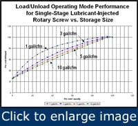
Figure 1. Load/unload operating mode performance as a function of storage capacity for a single-stage lubricant–injected rotary screw compressor.
Therefore, a system with a VSD compressor needs usable storage, which allows the VSD unit to start and load, and prevents short cycling of either the VSD or constant-speed compressor(s). For example, in a single-compressor system where the demand drops below the maximum turndown of a start-stop VSD compressor, the minimum usable storage is a function of the compressor’s capacity, turndown, control band and the allowable pressure decay during startup. If the lubricated VSD compressor has a 1,000-cfm capacity, an 80% turndown and blows down the sump when it stops, then the usable storage capacity multiplier is 1.2 (Table 2).
Therefore, the required usable storage to prevent more than 3-psi decay during startup is 1.2 X 1,000 = 1,200 gal. On the other hand, if the compressor only has a 50% turndown, the usable storage requirement increases to 3,000 gal. Worse yet, if the VSD compressor only has a 50% turndown and blows down the sump at restart, the usable storage requirement becomes 7,500-gal. From these examples, one can see that it’s best to ask about the VSD compressor’s operating mode, turndown and restart sequence before purchasing it.

Table 2. Capacity multiplier to determine required storage (gal) for start-stop VSD compressors (based on 3-psi allowable pressure decay at startup).
In a multiple compressor system using a VSD trim compressor, the required usable storage is determined by the control band, the acceptable pressure decay and the difference between the capacity of the constant-speed compressor and the turndown of the VSD compressor.
For example, let’s assume a system has a constant-speed compressor with a 500-cfm capacity, and a VSD compressor with a 460-cfm capacity and an 85% turndown. The VSD compressor’s turndown is 391 cfm, so the difference between the constant-speed compressor’s capacity and the VSD compressor’s turndown is 109 cfm. Therefore, given a 5-psi control band, for the constant speed compressor to have a 90-sec cycle time, there must be 899-gals of storage ((109 cfm/2/(5-psi/min)) * (1.5 min/2 min)) * 14.7 psia * 7.48 gal/ft3).
A 5-psi control band was used in this example because systems with a VSD compressor normally are controlled in a tighter pressure control band. Installing a VSD compressor that had only a 50% turndown would increase the usable storage requirement to 2,227 gal. On the other hand, installing a VSD compressor with a turndown greater than 500 cfm would eliminate the need for usable storage to prevent short cycling of the constant-speed compressor(s), but it would significantly increase the project cost.

Figure 2. The pressure drop across the dryer is 5 psi under load, but 0 psi when the compressor is unloaded.
Installing smaller load/unload trim compressors, a VSD compressor or load-sharing across variable-displacement or centrifugal compressors can reduce the required volume. In the case of centrifugal compressors, if the change in demand exceeds the compressor’s total turndown, one can increase the system turndown by installing a VSD rotary screw compressor. However, even with well-tuned controls, sufficient volume is still required to prevent the pressure swings that a hunting control valve on a centrifugal compressor causes.
Two ways to increase the usable storage are install more volume or increase the compressor control band. However, in most cases, large pressure swings are undesirable. So, most compressed air system discussions assume a maximum 10-psi control band.
{pb}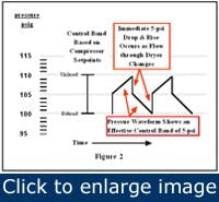
Figure 3. It’s possible for a nominal 10-psi control band to be only a 5-psi effective control band.
Many people believe they have a 10-psi control band if the compressor reload point is set 10 psi below the unload point, however, this normally results in a much narrower control band. For example, Figure 2 shows a compressed air system with only one compressor, but this discussion also applies to multiple-compressor systems where each compressor has a dedicated dryer and operates in local control mode. With the compressor operating in load/unload mode, the pressure drop across the dryer is 5 psi when the compressor is loaded and 0 psi when it’s unloaded, so the effective control band is 5 psi (Figure 3). In this example, the required usable storage is achieved by:
- Increasing the differential between the compressor’s unload and reload set points to 15 psi,
- Doubling the system volume or
- Controlling the compressor(s) off the system pressure.
Another option often recommended to resolve this matter is to install a receiver between the compressor and the dryer, but this might not increase the effective control band to 10 psi. The reason is that when the compressor loads and unloads, the pressure drop across the dryer is inversely proportional to the percentage of storage volume located upstream of the dryer.

Table 3 shows that if the majority of the storage volume is located upstream of the dryer, then it’s effective. However, if the majority of the storage is located downstream of the dryer, then it’s ineffective. In addition, for upstream storage to be effective, there can’t be any pressure drop between the compressor control signal location and the upstream receiver. To this point, the control signal isn’t always located at the discharge of the compressor package.
In many cases, the control signal point is located upstream of the aftercooler and moisture separator, whose pressure drop can vary from 2.5 psi to 6 psi. When combined with the dryer differential, the total can vary between 7.5 psi and 11 psi. So, it’s no wonder the compressor short-cycles when the differential between unload and reload set points is only 10 psi. As a result, the best that upstream storage can do, when the control signal point is located upstream of the compressor’s aftercooler, is eliminate 5 psi of the 7.5 psi to 11 psi pressure change that occurs when the compressor unloads.
When deciding whether to install the required storage, remember that an air receiver doesn’t need an electric cord.
Chris Beals is president of Air Systems Management, Inc. Contact him at [email protected] or (303) 771-4839.