Optimize compressed air storage to drive system-wide energy efficiency
Jump to:
P1 Storage capacity and load/unload control
P2 Storage capacity and pressure stability
P3 Storage to protect against equipment failure
The storage of compressed air in receiver tanks is very important to consider when excellent system energy efficiency is the goal. Among other things, compressed air that is stored in system air receivers can be used to increase the efficiency of the running air compressors and to help stabilize system pressure so lower average pressures can be used. It also can help the system to ride out large compressed air demands or major system events that might cause transient low pressure issues.
How much storage capacity does a system need? This is a common question and is typically subject to a number of different industry rules of thumb. Led by the efforts and recommendations of Compressed Air Challenge, many in the industry are now recommending a storage capacity of between 5 and 10 gallons per cfm for compressed air systems. Applying these sizes reduces the compressor cycle frequency substantially and saves significant power.
Storage capacity and load/unload control
Storage formula
The following formula can be applied to calculate the required compressed air storage under different conditions in your plant, and under many kinds of storage capacity conditions:
Where:
V = Receiver volume required, ft3
T = Time allowed for pressure drop, minutes
C = Intermittent demand, acfm
S = Compressor capacity minus process demand, acfm
Pa = Absolute atmospheric pressure, psia
P1 = Initial receiver pressure, psig
P2 = final receiver pressure, psig
In the past, the recommended storage receiver size was 1 gallon per each cubic foot per minute (cfm) of the system air compressor capacity. For example, if the compressor was a 100 hp, 400 cfm rated unit, then a storage receiver sized at about 400 gallons was used. This sizing guideline was common when most lubricated screw air compressors were running in inefficient modulation mode pressure control. (Modulation control is where the compressor inlet valve is progressively closed off by the local control system to control the output flow. In modulation mode, the power consumption only reduces 3 percent for each 10 percent reduction in flow.)
Over the years, load/unload control mode has become the most common control method because it is a more efficient way to run lubricated screw compressors than modulation mode at loads that are lower than the full compressor capacity. Load/unload controlled compressors cycle between loaded and unloaded condition at part loads. In load/unload control mode, the theoretical ideal power turn down is about 7 percent for each 10 percent reduction in flow. But with lubricated screw compressors, this turn down is affected by load/unload cycle frequency.
The characteristic cycle frequency of a load/unload compressor depends on the width of the compressor pressure band, the volume of the effective system storage, and the loading percentage of the compressor. The higher the cycle frequency, the less efficient the compressor runs at part loads, especially if it is a lubricant injected compressor. The changes to the power vs. flow characteristics with changing storage receiver sizes are shown in Figure 1.
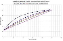
The load/unload state of the compressor is controlled by the setting in compressor pressure controller, usually set with a band which is 10 psi wide. If the old "1 gallon per cfm" rule is applied to a compressor with a 10 psi wide setting, the expected theoretical efficiency gain due to switching from modulation to load/unload control would not materialize because the load/unload cycle frequency is too high, as seen on the top dark blue curve in Figure 1. This problem has led compressor suppliers to upgrade the industry rule of thumb to "2 gallons per cfm". Increasing the capacity to this level reduces the cycle frequency by a factor of 2 but the compressors still have marginal efficiency at some part loads.
In examining Figure 1, if a compressor with 100 kW full load power and 1 gallon per cfm of storage capacity was operating at 40% load, it would consume about 82 kW. If that same compressor was working with 3 gallons per cfm of storage, the power consumption would reduce to about 68 kW for energy savings of 17%. This is still significantly different than the expected 55 kW power consumption for 33% savings if the ideal compressor curve is used to calculate the expected savings.
{pb}
Storage capacity and pressure stability
[sidebar id="7"]
Before discussing the improvement of pressure stability that goes hand-in-hand with larger storage capacity, let's go through a storage capacity primer. Let’s say you have purchased a large storage tank and it is sitting unpressurized out on the pad. How much air does it contain? If it is a 1,060 gallon receiver it will contain 1,060 gallons of atmospheric air pressurized to the local atmospheric pressure (14.5 psi above absolute zero for example). Since every 7.48 gallons contains one cubic foot, that receiver contains about 142 cubic feet (cf) of ambient air.
If one more atmosphere of air pressure is added to the receiver–assumed here to be 14.5 psi absolute–or another 142 cf, the pressure in the receiver will rise by 14.5 psi. This continues as more air is added to the receiver with each 142 cf (1,060 gallons) adding another 14.5 psi.
If you want to determine how much air to add in order to boost the pressure in the tank by 1 psi, simply divide 142 cf by 14.5 psi, with the result yielding 9.78 cf/psi. This number is important, because it indicates how much the pressure will change in the tank if a certain amount of compressed air is added or removed from the storage tank.
For example, if a compressed air powered machine uses 97.8 cf more than the compressor could produce, this air must be supplied by the receiver. For the tank in question, the pressure in the storage tank would drop 97.8 cf divided by the 9.78 cf/psi capacity of the storage receiver (i.e., 10 psi) during that event if all the air came from the tank storage. If the tank size was doubled, then the pressure would drop only 5 psi, and if tripled only 3 psi, and so on. This shows that if we desire pressure stability, and the compressed air system has high transient demands, then the way to protect production machinery from low pressure is often to add more storage.
Taking another example that illustrates this point, suppose we have a 100 hp (85 kW) compressor that is rated at 400 cfm operating in a system with 400 gallons (3.7 cf/psi) of storage capacity, sized using the 1 gallon per cfm rule of thumb. Perhaps the production machinery in this system starts to have problems if the system pressure drops below 90 psi. Let’s also assume that the compressor is operating at an unload pressure 110 psi and a load pressure of 100 psi.
If a transient one-minute 500 cfm demand event hits the system, the capacity of the compressor will be exceeded by 100 cfm and air will be consumed from the storage receiver while the system pressure drops. A worst-case scenario would be to have this demand hit the system when the system pressure is right at the 100 psi load point. If this was the case, the pressure would fall by 100 cf (the shortfall) divided by 3.7 cf/psi, or 27 psi per minute. At this rate it would take only about 20 seconds for the pressure to fall below the 90 psi pressure required by the production machinery. But if the storage capacity is increased to 5 gallons per cfm (2,000 gallons at 18.4 cf/psi) the pressure during this worst-case scenario would only fall by 5.4 psi during the one-minute event.
For these conditions, the old "1 gallon per cfm" storage capacity rule, or even 2 gallons per cfm, would not be adequate. The only alternative would be to run another compressor to supply the additional 100 cfm. If the other compressor was another 100 hp compressor, we can see by the curve in Figure 1 that it would cost about 70% of its full load power to run at 25% capacity (or about 60 kW), compared to no power consumed by a large storage tank. After the one-minute event the compressor would typically run at 25% power at zero flow for a cool down period before it could shut off, wasting even more power.
{pb}
Storage to protect against equipment failure
Another condition that might require more storage than the rule of thumb is when designing to protect the system against equipment failure. Using the second example above, if the 400 cfm compressor tripped off while running fully loaded, this would remove 400 cf per minute of compressor capacity from the system. If the 2,000 gallon system experienced this problem when the compressor was running at full load with the transient demand, the pressure would start to drop by 500 cfm divided by 18.4 cf/psi, or 27 psi per minute. If it takes 30 seconds to automatically start and load a backup compressor, and the backup is set to start at 95 psi, the pressure will have dropped 13.5 psi to 81.5 psi by the time the backup compressor saves the pressure, which is lower than our 90 psi minimum pressure requirement.
[sidebar id="7"]
If we wanted to ensure adequate pressure at all times, even with main compressor failure, then at least 5,420 gallons of storage (50.0 cf/psi) would need to be installed. The "2 gallons per cfm" rule would be inadequate, as the required size to protect this system is the equivalent to at least 13.6 gallons per cfm compressor capacity.
An alternative to this would be to jack the system pressure up by 10 psi to give the system more time for the spare compressor to start. However, for every 2 psi increase in pressure the loaded compressor consumes about 1% more power, reducing system efficiency for all operating hours.

Sizing for compressed air storage success
An example compressed system with a 60 hp 240 cfm compressor consuming 48 kW at full load is installed at a tire retread facility. The facility fills large autoclaves with compressed air so that the tire treads can be baked onto the tires under heat and pressure. The production tools need at least 90 psi for proper operation. The plant desires to run the compressor at 135 psi (the highest pressure the compressor is allowed to run) to give enough buffer to maintain adequate production pressure at all times, even when the autoclaves are filling. Peak plant demands during the busiest times are 200 cfm, not including the autoclave fills. The average shop flow is 60 cfm, and the autoclave fills take 200 cfm of flow for 10 minutes. What is the best approach to size the compressed air storage system for success?
Option 1: Sizing for efficiency
If the compressed air storage is sized for "1 gallon per cfm", the old rule of thumb, this compressor will consume about 66% of its full load power (0.66*48 kW = 32 kW) during average conditions. If we use the "2 gallon per cfm" rule of thumb, then the added storage, all other conditions remaining constant, will be reduced to about 53% of full load, or 25.5 kW for a savings of 7.5 kW. At 10 cents per kWh and full time operation of 8,000 hours per year, this higher level of storage would save $6,000/year in electricity costs.
Option 2: Sizing for peak
Under worst-case conditions, the shop would be at one of its production peaks at the same time an autoclave fill was initiated. Since the shop flow of 200 cfm leaves only 40 cfm of compressor capacity remaining, the remaining 160 cfm of air (200 cfm of autoclave flow minus 40 cfm remaining compressor capacity) must be supplied from a storage receiver. A flow of 160 cfm for 10 minutes requires 1,600 cf of total compressed air volume air from the receiver. Since the stored pressure is 135 psi, and the lowest pressure we can drop is 90 psi, a storage receiver would need to be sized at 40 cf/psi (1,600 cf/(135 psi-95 psi)= 40 cf per psi) if we are to leave a 10 psi buffer in storage. This results in a required tank that is 580 cf in size, or at least 4,340 gallons. If this size is used then autoclave can be filled at peak production times without having to start another compressor.
A secondary benefit to this size of receiver is that at average flows the compressor cycle time is much slower. The resulting capacity is equivalent to 18 gallons per cfm, and as a result the compressor would only consume about 46% of its full load power (or 22 kW), gaining an additional 2.5 kW of savings. In fact, at this size if the compressor was operating on a 15 psi wide load/unload pressure band, it would only be cycling no more than about 6 times per hour, making it possible to run the unit in start/stop mode. In this mode the compressor would consume only about 25% of its full load capacity at average flow (or 12 kW), for a savings of 75% over the base case small receiver system.
Option 3: Sizing for compressor failure
If it is desired to guard against compressor failure at worst-case conditions, and the backup compressor takes 30 seconds to start, then we need to do a third calculation. If the backup compressor is set to start at 94 psi and the lowest pressure allowed is 90 psi, then only 4 psi worth of storage remains with which to work in starting the backup compressor. We would require enough compressed air volume to supply the full plant peak flow (200 cfm) plus the autoclave fill (200 cfm) for the 30 second start time. This requires 400 cfm for 0.5 minutes, or 200 cf. This volume of air must come from only 4 psi of receiver pressure differential, so a storage receiver is required that has a capacity of 50 cf/psi (200/4 = 50 cf/psi works out to about 5,300 gallons). This is even larger than the size required for the autoclave fill.
About the Author
Ron Marshall
Ron Marshall first developed his skills as an industrial compressed air systems expert at Manitoba Hydro, where he worked for 38 years, supporting more than 600 energy efficiency projects. He now operates his own compressed air energy efficiency consulting firm where he provides technical advice, system auditing, and training. Ron is a level 2 instructor with Compressed Air Challenge and conducts training internationally. Contact him at [email protected].Want to learn more about compressed air? We would suggest sending key staff to one of our Compressed Air Challenge seminars to help them learn what is possible. To learn more about upcoming training opportunities visit the CAC calendar at https://www.compressedairchallenge.org/calendar.