Rotor balancing for bearing reliability
In brief:
- Even if a balanced shaft exhibits no vibration signature, it’s possible to have stresses present in the rotating elements between the bearings.
- Multi-element shafts should have each component balanced individually before being assembled into a finished unit.
- Every time the force on a bearing is reduced by a factor of two, its life increases by a factor of eight.
The purpose of balancing a rotor is to reduce the vibration that can damage the bearings that support it. Even if a new rotor wasn’t balanced well in the manufacturer’s shop, it’s possible to balance it in the field after installation. However, balancing only alleviates bearing deterioration. The internal stress might still exist, especially in a multi-element rotor. Let’s find out why field balancing suppresses only the phenomenon — the vibration on the bearings — not the stress in the rotor.
Static equilibrium
With a rotor running at a constant speed, the familiar equations of statics that dictate that the vector sum of both the forces and moments must equal zero are, of course, satisfied. The force arising from a constant angular velocity is:
Fc = mrω² (Equation 1)
Where:
Fc = centrifugal force
m = mass (imbalance weight)
r = radius of imbalance
ω = angular velocity (2*π*rpm/60)
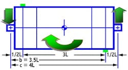
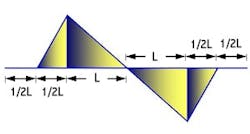
Figure 1 represents a symmetrically separated, two-plane rotor. If we ignore the rotor’s weight, we realize that the bearings react only to the imbalance. Equations 2 and 3 represent the forces acting on the right and left bearing, respectively.
Fr = (a-b)McRcω²/c (Equation 2)
Fl = -(a-b)McRcω²/c = -Fr (Equation 3)
McRc is the couple unbalance and, in this case, a = L, b = 3L, c = 4L. This implies that:
Fr = (L-3L)McRcω²/ 4L = -0.5 McRcω² (Equation 4)
Fl = -Fr = +0.5McRcω² (Equation 5)
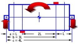
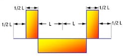
If we try to counterbalance the original moment through field balancing at two planes, again, symmetrically separated, but closer to the bearings, we have the situation depicted in Figure 2.
Equations 2 and 3 still apply, but with reversed signs. The additional compensating unbalance induces its own load on each bearing.
Fr = (3.5L-0.5L)mcrcω²/4L = 0.75 mcrcω² (Equation 6)
Fl = -Fr = -0.75 mcrcω² (Equation 7)
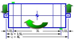
This only isolates one couple unbalance at a time. If they’re added by superposition, the forces on the bearings can cancel each other (Figure 3), if McRc = 1.5 mcrc.
The objective is to reduce the load on the supports to zero, at which time the bearings experience zero vibration. Theoretically, in the weightlessness of outer space, a perfectly balanced rotor, powered by a virtual driver, can rotate like a free body with no need for bearings.
There are many rotor configurations. The bearing span, distance between balance planes and location of balance planes relative to the support bearings, are relevant variables. Most importantly, if imbalance exists in any plane, the load distribution on the bearings might never be equal.
Although the goal of balancing is to reduce vibration levels to below accepted tolerance, it’s better to fine-tune the process instead of using only one standard — ISO1940/1, ANSI S2.19-1999, or VDI Std. 2060 (1966). The risk in using only one standard is that a heavily loaded bearing might never be balanced well enough and the lightly loaded bearing might be overbalanced.
Stress in the rotor
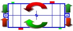
If no vibration is observed at the bearing pedestal, is the rotor well balanced? The answer is yes, but there can be a side effect — stress. Figure 4 depicts the bending stress distribution for the well-balanced rotor shown in Figure 3, with the maximum and minimum bending stress being:
Max bending = +0.5 mcrcω²L (Equation 8)
Min bending = -0.5 mcrcω²L (Equation 9)
On a rotating system, the stress reverses direction every revolution, a situation that can cause fatigue failure. A similar scenario for shear stress is shown in Figure 5, with the maximum and minimum shear stress being:
Max shear = mcrcω² (Equation 10)
Min shear = -0.5 mcrcω² (Equation 11)
We carefully determine the location and magnitude of the residual imbalance and mark it. Then, during the last step, we adjust each component (sequence or orientation) to reduce the vibration of the entire rotor assembly to somewhere below established tolerances. Although field balancing might zero out the vector sum of the forces on each bearing, it doesn’t eliminate the stress within the rotor. That’s why each disk on a multi-stage rotor should be micro-balanced individually.
| Han-Chian Gee, P.E., is Chief Reliability Engineer at Formosa Plastics Corp., Port Lavaca, Texas. Contact him at [email protected] and (361) 552-6871. |
It’s a good maintenance practice to balance each rotating component — shaft, impeller, and coupling — before connecting them into a final assembly. In many cases, however, it’s impossible, difficult, time-consuming or not cost-effective to find the planes that represent the exact sources of the imbalance. Under such circumstances, balancing an existing rotor assembly might be our only option. If so, balancing might not guarantee the rotor’s longevity, but it will save the bearings.
The point is that every time the force on a bearing is reduced by a factor of two, its life increases by a factor of eight. That is an economically sound trade-off for any plant.
About the Author
Han-Chian Gee
Han-Chian Gee is a chief maintenance engineer for Formosa Plastics Corp, Point Comfort, TX, one of the top PVC suppliers in the world. He has more than 30 years of experience on rotor dynamics and other related reliability practices and technologies. He is an ISO 18436-2 Category III certified analyst and a registered PE in the state of Texas. He previously worked at Aerospace Industrial Development Corporation (AIDC), Taiwan, on the fuselage, on a composite (graphite) design for speed brake, on a honeycomb horizontal stabilizer, and on the rudder for AT-3 jet trainer & Indigenous Defense Fighter (IDF). He can be reached at: [email protected]