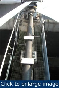
Figure 1. In this cooling tower spacer shaft configuration, the distance from the motor to the gearbox is more than 12 ft.
In brief:
- Spacer shaft alignment has two unique aspects. The amount of alignment correction at the motor can seem to be very large. And you are correcting two angles, one for each coupling.
- To achieve good, repeatable results, pre-alignment steps must be done. Inspect the coupling for wear prior to alignment.
- Minimize the soft foot under the motor before performing alignment. The difference in a 15-min alignment and an eight-hour alignment is often correcting the soft foot. Utilizing the soft foot function in laser alignment systems works well.
Many maintenance personnel have experience with aligning standard coupling configurations, such as a motor to a pump, but some are less confident when they’re asked to align cooling tower fans with spacer shafts.
What’s the big deal? It’s almost always too hot, too cold, or too wet. There’s usually lots of steps and ladder climbing involved, most of it carrying big wrenches, hammers, and pry bars. Most cooling towers seem to be built with the assumption that no one will ever need to get to the fan, gearbox, or shaft again, so there may not be a place to stand inside of the cell. And it’s a long way down to the basin.
Cooling towers fans with spacer shafts can be aligned just as accurately and easily as any other coupled machine, if you follow a few simple steps. The same principles apply to most other machines using spacer or line shafts.
Several configurations of cooling tower fan drives exist. A spacer shaft doesn’t need to be treated like a separate machine because it isn’t. It has no bearings or support mechanisms of its own. It must go where the driver and driven shafts take it. If you do happen to have a long spacer shaft with a center support bearing, the center support bearing must be treated like an additional machine component, and aligned as a machine train.
Spacer shaft alignment has two unique aspects. First, the amount of alignment correction at the motor can seem to be very large. While the distances across the coupling faces may be only a few inches, the faces of the couplings, and the shafts, form right angles. So the angles extend for several feet back to the motor or movable machine. When the distance between the driver and driven machines is several feet, the correction amounts at the motor feet can be ¼ in. or more, but the offset and angularity at the couplings may be within tolerance (Figure 1).
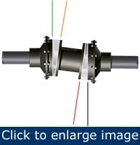
Second, you are correcting two angles, one for each coupling. There is really no offset, or parallel correction. If you get all four coupling faces aligned, the spacer shaft will go along (Figure 2).
Pre-alignment steps
As with any type of shaft alignment, to achieve good, repeatable results, pre-alignment steps must be done.
Figure 2. When the angular misalignment is reduced to near zero degrees across both coupling faces in the vertical and horizontal directions, the driving and driven shafts will be aligned.
Inspect the coupling for wear prior to alignment. There is no logic to performing a precision alignment, only to have to replace the worn or damaged components, and then align it again.
Make sure the surfaces onto which the motor and gearbox mount are free of dirt, rust, paint, or other debris that could get under the feet of these components. This will greatly simplify the alignment process, and reduce errors due to debris. Taking two minutes to clean the junk from underneath the motor feet is worth it.
Minimize the soft foot under the motor before performing alignment. The difference in a 15-min alignment and an eight-hour alignment is often correcting the soft foot. Utilizing the soft foot function in laser alignment systems works well. It can also be done manually with feeler gauges or shims in a two-step process.
- With all hold-down bolts loose in the motor, use a shim or feeler gauge to measure each foot in at least three places, to minimize angular and parallel soft foot. Correct to less than 0.005 in.
- With all hold-down bolts tights, loosen one foot, and recheck for soft foot in the same manner, this time correcting angular and parallel soft foot to less than 0.002 in.
- Or it can be done using dial indicators with magnetic bases, if the dial indicator can be located to sufficiently measure any soft foot movement.
Rarely can a dial indicator be properly placed to really measure for soft foot. Life will be much more pleasant if you will simply loosen the motor feet, feel around with a feeler gauge or shim for a soft foot, and correct it before you start aligning.
Confirm that the motor and gearbox input shafts are true, with a minimum of radial and axial runout of the shafts. Shafts and couplings with runout can be aligned, but may cause excessive vibration and wear of components. Runout is best checked by using a dial indicator and magnetic base to confirm radial and axial runout. Consult your manufacturer’s recommendations before aligning the cooling tower fan. In addition, long metal spacer shafts that sit for extended periods can become bowed. Check the center of the shaft to confirm that no shaft bow has occurred.
Sometimes, on a vibration service job to balance cooling tower fans, it’s discovered that the spacer shaft is bent. It’s a good idea to check it with a dial indicator before hauling everything up there.
The coupling backlash should be minimized to prevent erroneous readings. This can negatively affect alignment quality regardless of whether you are using dials or a laser system.
Roughing-in should be done to minimize the possibility of base-bound or bolt-bound conditions and should be done while the fan is in construction or commissioning stages, or after a gearbox or motor replacement. The roughing-in process for a cooling tower fan with a spacer shaft is different than a standard motor-pump configuration, since there may be several feet between the motor and the gearbox, and a 15-ft-long straightedge won’t work. It’s not difficult to rough in a spacer shaft with a dial or vernier caliper, by measuring the gap difference top to bottom, and side to side, for each coupling. An adequate alignment can be performed using this process, if your math skills are good and you take great care to keep up with your numbers. But it’s much easier, is much faster, and requires much less ladder climbing going back and forth between the couplings, to rough it in using the laser alignment tool.
It is also very common for a cooling tower drive to be bolt-bound, base-bound, or both. Don’t be afraid to move or shim the gearbox to eliminate a bolt-bound or base-bound condition. If you must move the gearbox horizontally to correct a bolt- bound situation on the motor, be mindful of blade tip clearance around the plenum. Also, if you experience a base-bound condition, where the motor is sitting too high, you can shim the gearbox slightly just under the inboard end of the gearbox.
A cooling tower fan using a spacer shaft can be roughed in with a laser alignment tool using a 7-step process.
- With your lasers in the 12 o’clock position, center both lasers onto the targets by adjusting the laser transmitters/receivers.
- Rotate the shafts to the 6 o’clock position.
- Note the location of the beam on the movable detector. Adjust the position of the beam striking the movable detector by moving the entire motor up or down half the distance of the change.
- Return to the 12 o’clock position, and re-center both detectors.
- Rotate to the 6 o’clock position again.
- Note the location of the beam on the stationary detector. Adjust the outboard motor feet to move this beam halfway back to its original position.
- Repeat the process at the 3 o’clock and 9 o’clock positions, to rough in alignment horizontally.
If your lasers have sufficient target size to measure at least 90° of rotation, skip all of this, and let the laser do the roughing in and the alignment in one step.
Once the roughing-in process is completed, or if you have sufficient range to take an initial measurement, continue with your alignment as you normally do.
If your laser tool does not have a spacer shaft function, the spacer shaft can be treated as one long coupling. Simply use the center of the spacer shaft as the center of the coupling. Once the motor shaft is aligned to the gearbox input shaft, the spacer shaft will also be in alignment.
There are additional considerations that might need to be addressed to ensure quality alignment of a cooling tower fan.
Condensate vapor: No laser alignment system will shoot through a steam bath. If possible, perform your alignment with the system down and the basin drained. If it is a multi-cell tower and cannot be drained, run the fans on each side of the fan you are aligning, to help assure decent air flow and minimize any condensate in the air. Also, if you have to perform an alignment in a hard rain, put up a tarp to prevent rain from disturbing your laser beams.
Leveling: The entire structure should be level. Special care should be taken to level or plumb fan shafts. Also, most gearboxes should be reasonably level to provide proper lubrication.
Blade tip clearance: To provide effective cooling and to reduce vibration, fan blade tips should be equal across the plenum, or fan shroud. Assure proper blade tip clearances around the periphery of the fan. If you must move the gearbox to correct a bolt bound situation, be sure to check the blade tip clearance.
Structural integrity: All bolting systems should be tight, with minimal flexing of the cooling tower. This is especially true with non-concrete cooling towers. Routine maintenance of the bolting systems should be conducted to provide long life of the system. Loose bolting can also cause shifting in the tower, which can make alignment much more difficult.
Accessibility: Often, cooling towers are placed on the roofs of buildings to minimize the adverse affects of heat and condensate and to place the tower in a good position for steady air flow. As such, cooling towers are often overlooked as part of the maintenance process. In addition, their heights, placement near the edges of buildings or tall structures, and the proximity of large rotating components necessitate utilizing safe working procedures. Consult management, or plant safety department to make sure all safety considerations are followed.
Guarding: A large, rotating shaft and fan should be guarded to prevent the chance for injury. Guards usually must be removed to perform alignment. Consult your management or plant safety department to make sure all safety considerations are followed.
Shaft penetrations: In addition, large cooling towers utilizing spacer shafts are often configured with the motor outside of the cooling tower fan section to remove the motor from the high humidity area. This can make aligning the fan shaft a more difficult process. The plenum or fan shroud should have a large enough hole to facilitate performing shaft alignment. If it does not, cut holes small enough for the beams to go through the plenum. On newer laser alignment systems using inclinometers, only three holes, spaced at least 30° apart, are needed. However, spacing them at the 9, 12, 3, and/or 6 o’clock positions — only three of the four are needed — will give a wider span, will give a more accurate measurement, and will look like it’s supposed to be there.
Stan Riddle is a technical trainer for VibrAlign (www.vibralign.com). Email him at [email protected].


