Testing the insulation resistance of rotating machinery
When the IEEE-SA Standards Board approved a revision of IEEE Standard 43-1974 by the Electric Machinery Committee of the IEEE Power Engineering Society, the document became IEEE Standard 43-2000, the IEEE Recommended Practice for Testing Insulation Resistance of Rotating Machinery.
This revision underscores the need for upgrading current practices to accommodate changes and improvements in insulating materials and the value of higher voltage testing that reveals otherwise hidden flaws. A complete regimen of every proven test is not practical, except for the most critical and expensive equipment.
Studies have shown testing motors using 10 kV provides a significant extra dimension for a testing program. The leakage current the higher voltage induces reveals incipient tracks not seen at lower voltages. Also, the increased sensitivity affords accurate readings from time of installation to reduce the asset's life cycle cost.
Some details
According to the IEEE, Standard 43-2000 is intended for individuals and organizations that:
- Manufacture rotating machines.
- Have responsibility for accepting new rotating machines.
- Maintain rotating machines.
- Operate rotating machines.
IEEE Standard 43-2000 recommends a procedure for measuring insulation resistance of armature and field windings in rotating machines rated one hp, 750 watt or greater and applies to synchronous machines, induction machines, DC machines and synchronous condensers. It also recommends the insulation test voltage (based on winding rating) and minimum acceptable values of insulation resistance for AC and DC rotating machine windings.
Test voltage
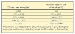
Table 1 provides guidelines for the intensity of DC voltage to be applied. Note that voltages to 10 kV are recommended for windings rated at more than 12 kV.
Table 1. Insulation resistance test dc voltage guidelines.
Of course, at some point applying higher voltage to gain smaller bits of information becomes counterproductive, and eventually damaging to the item under test. Following standards such as IEEE 43 helps avoid such pitfalls.
When phases are tested simultaneously, the data only reveals the insulation to ground. The revised standard recommends isolating each phase and testing them sequentially, if feasible, to allow comparisons between phases. The two phases not being tested should be grounded to the same point as the stator core or rotor body.
Insulation resistance measurements are to be made with external equipment (cables, capacitors, surge arresters, and the like) disconnected and grounded. Use a common ground to prevent ground circuit losses that could affect the results.
When a designated test voltage is critical, it's judicious to check the insulation tester's load characteristics. This is usually presented as a graph of test voltage versus resistance of the applied load. Insulation testers have limited current output, which prevents further damage to degraded insulation. The applied voltage can only decrease when the tester reaches maximum current output.
Therefore, the actual test voltage may not necessarily be the selected value. This is acceptable if testing determines the insulation is unfit to be called insulation. The test voltage should exhibit a rapid rise to the full selected output while it works against a resistance value commensurate with that of minimally acceptable good insulation (one to five megohms).
Much of the critical lower end of the scalewhere values suggest the need for preventive maintenancewill not be tested at the selected voltage. The loaded-down test voltage won't fully probe the insulation's condition, leaving a false sense of security as the result.
Test types and acceptable values
One of the trickiest tasks in maintenance testing, especially for new personnel, is interpreting readings. The IEEE standard provides a reliable and recognized means for interpreting these results. The standard recommends performing both the insulation resistance test and the polarization index test, if possible. It recommends using a testing history to track changes. If a history isn't available, the standard provides minimum values for both tests to estimate the winding's suitability. These are the lowest values at which a winding is recommended for an overvoltage test or for operation.
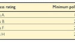
Table 2 shows recommended minimum values for the polarization index test are based on the insulating material's thermal class and apply to every insulating material, regardless of application, per IEC 60085-01: 1984. The polarization index test is not applicable to uninsulated field windings. Be aware that a polarization index greater than eight for varnished cambric, shellac mica-folium or asphaltic stator windings may indicate the insulation has aged thermally and may be at risk of failure.
Table 2. Recommended minimum values for the polarization index test.
Even though an item with little capacitance is in perfect working order, it exhibits a flat polarization index. Also, the IEEE points out one-minute readings in excess of 5,000 megohms are the product of especially small leakage currents that voltage instability, humidity and test connections can influence excessively, rendering polarization index results unsuitable. Testing at higher voltages, with increased range and sensitivity, can provide a counterweight to this problem.
Some new insulating material is characterized by a smaller degree of absorption than familiar types. A 10-minute reading on such insulation probably would not exhibit the expected degree of rise. This new phenomenonwhen interpreted in the established mannercan lead to confusion about the test results. That's why the IEEE extended the concept of polarization index to include one- and five-minute readings, and even 30-second and one-minute readings.
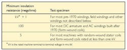
The recommended minimum insulation resistance after one minute at 40C can be determined from Table 3. The minimum resistance of one phase of a three-phase armature winding tested with the other two phases grounded should be approximately twice that of the entire winding. If each phase is tested separately (with guard circuits used on the phases not under test), the observed minimum resistance should be three times the entire winding.
Table 3. Minimum acceptable resistance values.
Large: a useful concept
Remember, infinity is not a measurement. It indicates only that the tested resistance is beyond the tester's range. This popular method of recording test results owes much of its acceptance to long-established instrumentation that affords only a basic measurement range.
While infinity is a reliable benchmark indicating the test item will operate for the immediate future, it provides little useable information for a preventive/predictive maintenance program aimed at eliminating unnecessary testing of equipment in prime condition, while at the same time maximizing the effectiveness of the testing regime. On the other hand, testing with even higher voltages pushes sensitivity into the teraohm range, which enormously enhances the capabilities of such a program.
When testing for polarization index, the measurement range has more than just a limiting effect on the usefulness of the resultsit can defeat the procedure completely. Calculating a polarization index requires the testing device to sense a value for 10 minutes. If the device over-ranges within that time frame, no value can be calculated. But, higher test voltages extend the measurement range and allow capturing that 10-minute reading for a polarization index where it couldn't at a lower output.
The machine's rating determines whether the motor windings must achieve the minimum value for either the insulation resistance test or polarization index test, or must achieve the minimum for both tests (see Table 4).
Table 4. Machine rating determines testing hurdle.
Note the IEEE advocates multiple tests plus compromise in the interest of practicality. The standard provides a general reference for fine tuning a testing program. Furthermore, both polarization index and insulation resistance tests, performed at appropriate voltages, are useful, if not imperative, before subjecting equipment to stress tests like high-pot and step voltage. The more general polarization index and insulation resistance tests reveal large-scale deterioration, while the stress tests capture elusive intermittent problems, such as localized mechanical damage and voids within the insulation.
Graeme Thomson is a vice president and Jeff Jowett is senior applications engineer at Megger. They can be reached at (610) 676-8500.


